Monday, September 15, 2014
Protection device speakers

In life, frequent situations where, for whatever reason speakers connected to an audio amplifier, the power of which exceeds the maximum allowed for a system that, on the one hand, often produce the best sound quality, increase the dynamic range, with another - increases the risk of damage due to overload dynamic heads. This is especially true when using the speaker on school, student, youth parties, where the acoustics are often connected to the first that fell known good amplifier that is "powerful." To prevent damage to the speakers when applying for her power, exceeding the nominal, it is necessary to equip the unit overload protection, built-in speakers and requires no additional power supply. Schematic diagram of such a device designed to protect the AC power 10 ... 35 W is shown in below
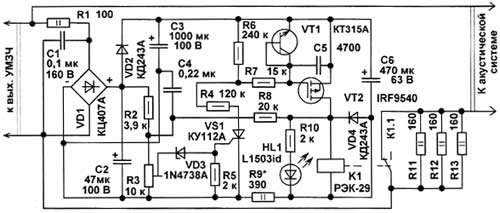 |
| Protection device speakers circuits |
Also in case of overload tripping SS, this device also protects it from damage by the dynamic head in the event of failure of the transistor amplifier and its output appears on the DC voltage. The device is connected to the output of the power amplifier audio frequency. The AC voltage is rectified by a bridge diode VD1. Resistor R1 eliminates the influence of a job amplifier. The rectified voltage is smoothed oxide capacitors NW, C2. While the output power of the amplifier does not exceed the maximum allowable for the AU, the voltage at the capacitor C2 is small, the zener diode VD3 closed, hence also closed and SCR VS1. In the micro-current SCRs of this type are controllable, ie, they can close the control voltage. Since VS1 is closed and will be closed transistor VT2. K1 relay contacts are closed, dynamic head at AU will do 100% of capacity. As soon as the output power of the amplifier exceeds permissible for AC voltage on C2 increases so that opens zener VD1, open SCR VS1 and the transistor VT2, K1 relay contacts open, the power supplied to the speakers will be limited by resistors R11-R13. These load resistors are a power amplifier, which improves stability of the amplifier in case of disconnection of speaker system, moreover, these resistors reduces arcing between the relay contacts when closing and opening. When protection against overload LED lights HL1. Transistor VT1, emitter junction which operates as a diode with a micropower voltage stabilization 7 ... 12 V protects the FET from the breakdown of a gate insulator. Once the voltage at the amplifier output is reduced, zener VD3 closes closed VS1, VT2, relay K1 is closed, on the AU will come back full power. Resistor R8 introduces small hysteresis to prevent cyclic circuit-opening relay contacts at a constant power output, slightly higher than the threshold. R9 resistor reduces the current through the relay coil by opening its contacts, capacitor C6 accumulates enough energy required for reliable operation of the relay.
When placing the speaker structure within the housing structure elements operate in a fairly strong vibrations in a wide range of sound frequencies produced by the dynamic head, moreover, in some cases, should also be considered an alternating magnetic field from the dynamic head. PCB should be located at a maximum distance from the open magnetic systems dynamic heads.
The device used fixed resistors MLT, Cl-4, C2-23 or imported analogues. Trimmer R3 is desirable to use a sealed enclosure, for example, SP4-1, GPA-16c, SP5-16A, SDR-19a-3 SP4. After setting up the rotation axis of the resistor must be assigned a drop of paint. Capacitor C1 terephthalate film ethyl K73-17, K73-9 or similar. C4 - ceramic K10-17, CM-5, oxide capacitors - K50-35 or imported analogues. NW capacitor can be formed from two 470 uF (provided on the circuit board). If necessary, the capacitor C6 also be used for the operating voltage of 100 V. In the case when the device is applied with amplifiers having a supply voltage output stages more than ± 50 V electrolytic capacitors need to be at the voltage of 160 V, the power and the resistance of resistors Rl, R2 , R9 also need to increase. Capacitors NW, C6 set parallel to the PCB, and further secured with wire clamps on it. Diode bridge can be replaced by a similar low-power, for example, DB103-DB107, RB153-RB157 or make up of four rectifier diodes with a working voltage of at least 100 V. Instead KD243A can install any of a series of KD243, KD247, KD208, KD105, 1N4002-1N4007. 1N4738A Zener diode can be replaced by KS175A, KS175ZH, KS126K LED - any other. Instead trinistor KU112A can apply CG 112 AM in the TO-92. N-channel field effect transistor in this embodiment IRF9540 can operate without the heat sink. Its maximum drain-source voltage of 100 V, the domestic counterpart - KP785A. Instead, the transistor can be used IRF9634, KP796A having UCH MAX> 250 V. Instead KT315A can apply any of the series KT312, KT315, SS9014. Relay K1 - REC-29, passport DUSCH4.501.56.Resistance of the coil of the relay about 950 ohm stable switching contacts occurs at a voltage of 15 V, the minimum voltage retention - 7 V. This type of relay modules used in the control of domestic TV USTST. For replacements, consider the fact that the contacts of the relay must commute significant current.
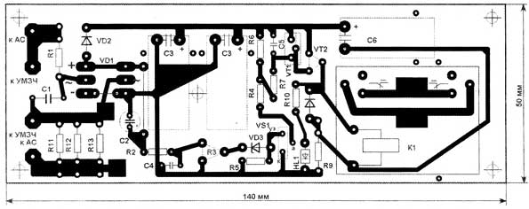 |
| PCB protection device speakers |
The apparatus may be mounted on a printed circuit board size 140x50 mm, wherein all the elements are installed than the LED. On Figure 2shows the circuit board from the conductors.
From the installation fee is desirable to cover three or four thin layers of epoxy glue. Each subsequent layer is applied after setting the previous one. Fee is attached to the body with five screws inside AU MOH or screws. If possible it is desirable to close deaf thick-walled (> 0.5 mm) casing, which also reduce the probability of failure of the device due to vibrations in the powerful speakers, as well as reduce the likelihood of contact bounce relay.
Manufactured author two instances these devices are used in conjunction with speakers 15AS-220, which uses dynamic head 25GDN-3-4.These systems start to wheeze and rattle when the input power more than 40 watts. Protection threshold set to 25 watts. These speakers are powered by an amplifier "Orbit UM-002 stereo",
which is able to develop power above 50 watts at 4 ohms. Other two copies installed in homemade sealed AC collected on broadband heads 10GDSH-1 powered by an amplifier "Corvette 50U-068 C". On threshold of protection is also installed at the rate of 25 watts of amplifier at 4 ohms. If you are working with powerful speakers (> 35 ... 5O W) and a powerful amplifier SCR will close at too low power for this case, the resistance of the resistors R4 and R7 can be doubled.
This device can be modified by setting instead of fixed resistor R2 thermistor NTC resistance of 3.3 ... 4.7 ohms at 25 ° C, which, through a pad of heat conductive rubber should be rigidly secured to the magnetic system, a powerful low frequency driver. In this case, strong heating of the magnetic system will include device protection with less output power amplifier.
Original article sourse cxem.net
Subscribe to:
Post Comments (Atom)
No comments:
Post a Comment