Sunday, September 21, 2014

Efficient LED Blinking for Embedded Systems

Smart hardware design can simplify the embedded software and make it more reliable. Designers use blinking LED signals to indicate different status and for inbuilt testability. Making an LED array blink requires an individual software loop for each LED or an individual timer and specific software to serve it. This can be an issue in a system that uses low-level MCUs which provide limited resources.

Efficient

Fig. 1: Circuit for efficient LED blinking for embedded systems


The schema presented here solves this problem by adding a simple hardware comprising low-cost inverters with Schmitt trigger for blinking as many LEDs as required.

Circuit and working
Fig. 1 shows the schema for efficient LED blinking for embedded systems. It uses different arrangements to make five different LEDs (LED1 through LED5) blink at individual rates. The schema is built around 74HC14 (IC1) containing six inverters with Schmitt triggers at the inputs. The frequency of blinking is usually selected in the 0.2-20Hz range.


The combination of inverter N1, resistor R1 and capacitor C1 is used as a square wave generator to blink LED1. LED1 blinks when output OUT0 from the MCU is high and goes off when output OUT0 is low.

The combination of inverter N2, resistor R2 and capacitor C2 works as a second square wave generator that makes LED2 blink. LED2 blinks when output OUT1 of the MCU is low and glows constantly when the output is high due to reverse orientation of D2.


Sometimes an LED needs more current than that provided by a single inverter. In that case, two or more inverters can be connected in parallel. Such an arrangement is made using inverters N3 and N4, resistor R3 and capacitor C3. The direction of diode D3 determines the logic of control of LED3 as indicated in the previous arrangements.

If you want two LEDs blinking alternately, the setup is made using inverters N5 and N6 together with resistor R4 and capacitor C4.

When OUT3 is low, LED4 is ‘off’ and LED5 is ‘on.’ When OUT3 is high, LED4 and LED5 blink alternately. The frequency of blinking in all the cases depends on the value of the adjoining resistor and capacitor.


Fig. 2: An actual-size, single-side PCB for efficient LED blinking for embedded systems


Fig. 3: Component layout for the PCB


Construction and testing
An actual-size, single-side PCB for efficient LED blinking for embedded systems is shown in Fig. 2 and its component layout in Fig. 3. The PCB provided is only for learning purpose and can be enclosed in a suitable case.

To test the schema, measure input supply at TP1. It should be around 5V DC with respect to TP0. Now make OUT0 high and measure the frequency at TP2. It should be around 2.5 Hz. Similarly, measure the frequencies at test points TP3, TP4, TP5 and TP6 as shown in the test points table.


Sourced by: Efy: Author : Petre Tzv. Petrov 
ReadMore..

Temperature Reference

It is often difficult to properly calibrate a temperature sensor since there is no suitable aid for doing so available. This article, which describes a temperature reference source, aims at putting this right. Since the source is made variable, the reference temperature may also be used for adjusting thermostats correctly. This may prove useful in the case of the recently published Titan 2000 audio power amplifier. The diagram shows how a Type BDV64 power transistor, T1, is used to provide a regulated-heat source and a calibrated sensor Type LM35 (IC2) monitors the resulting temperature. The two devices are mounted on a common heat sink.

temperature
At the same time, good thermal coupling between IC2 and the sensor to be calibrated is of paramount importance. Circuit IC1 functions as an on/off switch and actuates the power transistor (heater) when the temperature drops below the set value. The desired temperature is set with potentiometer P1. The better the thermal coupling, the smaller the hysteresis of the system. The circuit operates as follows. The output of IC1 controls power transistor T1. The specified values of resistors R4 and R5 ensure that the current through the transistor is not greater than 0.5mA.

This results in a dissipation of not greater than 6W. Sensor IC2 is powered by a regulated 5 V supply. Its output is a direct voltage of 10 mV °C–1. With component values as specified, the temperature may be set with P1 between +20 °C and +74 °C. Given these data, it is fairly simple to construct a suitable scale for the potentiometer. Almost any power transistor in a TO3P case and an amplification factor of ≥ 1000 may be used for T1.
ReadMore..

Saturday, September 20, 2014

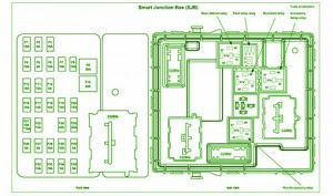
Fuse Box Ford 2002 F 350 Diesel Junction Diagram

Fuse Box Ford 2002 F-350 Diesel Junction Diagram - Here are new diagram for Fuse Box Ford 2002 F-350 Diesel Junction Diagram.

Fuse Box Ford 2002 F-350 Diesel Junction Diagram


Fuse
Fuse

Fuse Panel Layout Diagram Parts: generic electronic module GEM connection, one touch down relay, accessory delay relay, interior lamp relay, horn relay.
ReadMore..

Fuse Box Ford 2005 SUV Odometer Diagram

Fuse Box Ford 2005 SUV Odometer Diagram - Here are new post for Fuse Box Ford 2005 SUV Odometer Diagram.

Fuse Box Ford 2005 SUV Odometer Diagram


Fuse
Fuse

Fuse Panel Layout Diagram Parts: trailer tow park lamp, park lamp, ignition switch, powertrain control module, fuel pump relay, main fan relay, passive anti theft system, high mounnted stop lamp, stop lamp, powertrain control module, brake pedal position switch, instrument cluster, diagnostic connector, power mirror switch, audio unit, canister vant, power seats, sunroof, compass, radio, power window, suwoofer, low eams, horn.
ReadMore..

Whistling Kettle Wiring diagram Schematic

Most electric kettles do not produce a whistle and just switch off when they have boiled. Fitting a box of electronics directly onto an electric kettle (or even inside!) to detect when the kettle has boiled is obviously out of the question. The schema shown here detects when the kettle switches off, which virtually all kettles do when the water has boiled. In this way, the electronics can be housed in a separate box so that no modification is required to the kettle. The box is prefer-ably a type incorporating a mains plug and socket. 

Cap

In this application, the current flowing in coil L1 provides a magnetic field that actuates reed switch S1. Since the current drawn by the kettle element is relatively large (typically 6 to 8 amps), the coil may consist of a few turns of wire around the reed switch. The reed switch is so fast it will actually follow the AC current flow through L1 and produce a 100-Hz buzz. The switching schema driven by the reed switch must, therefore, disregard these short periods when the contacts open, and respond only when they remain open for a relatively long period when the kettle has switched off. 

Circuit diagram :

Whistling Kettle Circuit Diagram
 
The schema is based on a simple voltage controlled oscillator formed around T2 and T3. Its operation is best understood by considering the schema with junction R4/R5 at 0 V and C4 discharged. T2 will receive base current through R5 and turn on, causing T3 to turn on as well. The falling collector voltage of T3 is transmitted to the base of T2 by C4 causing this transistor to conduct harder. Since the action is regenerative, both transistors will turn on quickly and con-duct heavily. C4 will therefore charge quickly through T2’s base-emitter junction and T3. Once the voltage across C4 exceeds about 8.5 V (leaving less than 0.5 V across T2’s b-e junction), T2 will begin to turn off. This action is also regenerative so that soon both transistors are switched off and the collector volt-age of T3 rises rapidly to +9 V. With C4 still charged to 8.5 V, the base of T2 will rise to about 17.5 V holding T2 (and thus T3) off. C4 will now discharge relatively slowly via R5 until T2 again begins to conduct whereupon the cycle will repeat. The voltage at the collector of T3 will therefore be a series of short negative going pulses whose basic frequency will depend on the value of C4 and R5. The pulses will be reproduced in the piezo sounder as a tone. 

The oscillation frequency of the regenerative schema is heavily dependent on the voltage at junction R4/R5. As this voltage increases, the frequency will fall until a point is reached when the oscillation stops altogether. With this in mind, the operation of the schema around T1 can be considered. In the standby condition, when the kettle is off, S1 will be open so that C1 and C2 will be discharged and T1 will remain off so that the schema will draw no current. When the kettle is switched on, S1 is closed, causing C1 and C2 to be discharged and T1 will remain off. C3 will remain discharged so that T2 and T3 will be off and only a small current will be drawn by R1. Although S1 will open periodically (at 100 Hz), the time constant of R1/C1 is such that C1 will have essentially no voltage on it as the S1 contacts continue to close. 

When the kettle switches off, S1 will be permanently open and C1/C2 will begin to charge via R1, causing T1 to switch on. C3 will then begin to charge via R4 and the falling voltage at junction R4/R5 will cause T2/T3 to start oscillating with a rising frequency. However, once T1 has switched off, C3 will no longer be charged via R4 and will begin to discharge via R3 and R5 causing the voltage at R4/R5 to rise again. The result is a falling frequency until the oscillator switches off, returning the schema to its original condition. As well as reducing the current drawn by the schema to zero, this mimics the action of a conventional whistling kettle, where the frequency rises as more steam is produced and then falls when it is taken off the boil. 

The schema is powered directly by the mains using a ‘lossless’ capacitive mains dropper, C6, and zener a diode, D2, to provide a nominal 8 V dc supply for the schema.  A 1-inch reed switch used in the prototype required about 9 turns of wire to operate with a 2-kW kettle element. Larger switches or lower current may require more turns. In general, the more turns you can fit on the reed switch, the better, but do remember that the wire has to be thick enough to carry the current. It is strongly recommended to test the schema using a 9-volt battery instead of the mains-derived supply voltage shown in the schema diagram. A magnet may be used to operate S1 and so simulate the switching of the kettle. 

Warning. This schema is connected directly to the 230-V mains and none of the components must be touched when the schema is in use. The schema must be housed in an approved ABS case and carry the earth connection to the load as indicated. Connections and solder joints to components with a voltage greater than 200 volts across them (ac or dc) must have an insulating clearance of least 6 mm. An X2 class capacitor must be used in position C6.
ReadMore..

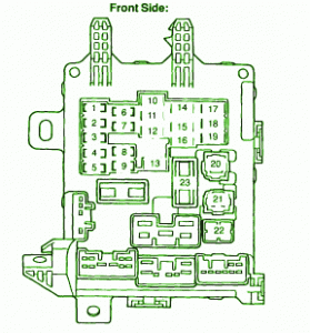
Fuse Box Toyota 1996 Corolla Passenger Side Kick Panel Diagram

Fuse Box Toyota 1996 Corolla Passenger Side Kick Panel Diagram - Here are new post for Fuse Box Toyota 1996 Corolla Passenger Side Kick Panel Diagram.

Fuse Box Toyota 1996 Corolla Passenger Side Kick Panel Diagram


Fuse
Fuse

Fuse Panel Layout Diagram Parts: turn signal light, emergency flasher, starting system, anti lock brake system, rear window defogger, gauges and meter, open door warning, back up light, air conditioning system, windshield wiper and washer, interior light, trunk light, clock, radio, cassette tape player.
ReadMore..

Fuse Box Diagram Of 2007 Kia Rio5

Fuse Box Diagram Of 2007 Kia Rio5
The following circuit shows about Fuse Box Diagram Of 2007 Kia Rio5. The parts fuse panel consist of :power window, air bag, hazard warning light,.amplifier, heated mirror, cigar lighter, air bag, sensor, ignition coil, lamp, abs system, ignition coil, daytime running light, sunroof, headlamp, wiper, instrument cluster, fog lamp.
ReadMore..

Flat Battery Indicator Small Circuit

This small circuit was developed to monitor the battery in a model hovercraft. The lift in the model is produced by an electric motor driving a fan. To avoid the possibility of discharging the rechargeable battery pack too deeply, the design lights a conspicuous LED mounted on the model when a preset threshold voltage is reached. The circuit only uses a few components, which helps keep the total weight of the model down. The circuit connects to the model only across the two points where the voltage to be monitored can be measured. These also supply power to the circuit.

The best place to connect the circuit is not at the battery terminals, but rather at the motor connections. The circuit is suitable for use with nominal battery voltages of 4.8 V to 9.6 V (four to eight 1.2 V cells). For example, if there are six cells in the battery, its nominal terminal voltage will be 7.2 V. A discharge threshold voltage of around 1 V per cell is appropriate, which means that for six cells the threshold is 6 V. We now need to set the voltage UZ across the adjustable Zener diode D1 (an LM431) to about 0.5 V less than the threshold voltage at which we want LED D2 to light.

Flat Battery Indicator  Circuit Diagram


This voltage is controlled by the choice of the value of resistor R1. As indicated in the circuit diagram, this is done with the help of a trimmer potentiometer (R1.A) with a fixed resistor (R1.B) in series. Using the suggested values (10 kΩ for both the potentiometer and the fixed resistor) allows the discharge threshold voltage to be set between about 5.5 V and 8 V. For lower or higher voltages R1.B should be made correspondingly smaller or larger. Once the desired value of UZ has been set the total resistance (R1.A plus R1.B) can be measured and a single fixed-value resistor of this value substituted at R1.

In the example mentioned of a six-cell battery, a voltage of 7.2 V will appear at the emitter of T1 when the battery is charged. At its base is UZ, which should be 5.5 V (6 V – 0.5 V) in the case of a discharge threshold voltage of 6 V. As long as the battery voltage remains at least 0.5 V higher than UZ, T1 will conduct and T2 will block, with the result that LED D2 will not light. If the battery voltage should fall below about 6 V (UZ + 0.5 V), T1 will block, T2 will conduct and LED D2 will light. To ensure stable operation of the circuit R6 provides a small amount of switching hysteresis. By adjusting the resistor value between 100 kΩ and 220 kΩ the amount of hysteresis can be varied.

The current drawn by the circuit itself is less than 5 mA (as measured with a battery voltage of 7.2 V). When the LED lights an additional 10 mA (the LED current) is drawn, for a total of around 15 mA. The adjustable Zener diode can be replaced by a fixed Zener with a voltage 0.5 V less than the desired threshold. Resistors R1 and R2 can then be dispensed with. A flashing LED can be used for D2 (without series resistor R7). An acoustic alarm can be provided by replacing D2 and R7 by a DC buzzer with a suitable operating voltage.
ReadMore..

Friday, September 19, 2014

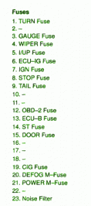
Fuse Box Toyota 2000 Corolla CE Instrument Panel Diagram

Fuse Box Toyota 2000 Corolla CE Instrument Panel Diagram - Here are new post for Fuse Box Toyota 2000 Corolla CE Instrument Panel Diagram.

Fuse Box Toyota 2000 Corolla CE Instrument Panel Diagram


Fuse
Fuse

Fuse Panel Layout Diagram Parts: wiper fuse, stoplamp fuse, taillight fuse, noise filter, I/UP fuse, ECU-IG fuse, ignition fuse, turn fuse, gauge fuse, power steering fuse, door fuse, cigar lighter, defogger, power window.
ReadMore..

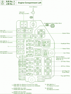
Fuse Box Toyota 1995 Supra Engine Compartment Diagram

Fuse Box Toyota 1995 Supra Engine Compartment Diagram - Here are new post for Fuse Box Toyota 1995 Supra Engine Compartment Diagram.

Fuse Box Toyota 1995 Supra Engine Compartment Diagram


Fuse
Fuse

Fuse Panel Layout Diagram Parts: A/C magnetic clutch relay, fog light relay, headlight relay, heater relay, fan relay, ABS system, starter relay, daytime running light, horn relay, dimmer relay.
ReadMore..

Fuse BOx BMW Z3 Underdash 1996 Diagram

Fuse BOx BMW Z3 Underdash 1996 Diagram - Here are new post for Fuse BOx BMW Z3 Underdash 1996 Diagram.

Fuse BOx BMW Z3 Underdash 1996 Diagram


Fuse
Fuse

Fuse Panel Layout Diagram Parts: ABS system, motorsport, airbag, air conditioning, automatic transmission, anti theft sytem, cigar lighter, clock, connector for optional, cruise control, cruise seats adjustment, electronic immobilizer, exhausy gas diagnosis, fuel pump, headlight cleaning system, heated seat window, heated blower, brake light, parking light, reversing light, side ligth, low beam headlight, interior light, high beam headlight.
ReadMore..

Fuse Box Toyota 93 Camry 2200 Diagram

Fuse Box Toyota 93 Camry 2200 Diagram - Here are new post for Fuse Box Toyota 93 Camry 2200 Diagram.

Fuse Box Toyota 93 Camry 2200 Diagram


Fuse
Fuse

Fuse Panel Layout Diagram Parts: ABS ECU, door lock control relay, cooling gan ECU, center air bag sensor, fuse/relay block, integration relay, A/C amplifier, shift lock control ECU, daytime running light relay,fuse relay, engine control module, electronic control transmission ECU, junction block, cruise control ECU.
ReadMore..

2 x 30W dual bridge car radio amplifier

Circuit Diagram:
2 x 30W dual bridge car radio amplifier TDA7394


ReadMore..

Fuse Box Toyota 2008 Prius Diagram

Fuse Box Toyota 2008 Prius Diagram - Here are new post for Fuse Box Toyota 2008 Prius Diagram.

Fuse Box Toyota 2008 Prius Diagram


Fuse
Fuse

Fuse Panel Layout Diagram Parts: Power outlet, Power windows, Multi information display, Electric power steering, Gaug and meter, Power windows, Rear Window defogger, Multi-information display, Air conditioning system, Hybrid system, Tail lights, License plat light, Parking light, Multi information display, Clock, Back up light, Emergency flasher, Power windows, On-board diagnosis system, Stop light, Power door clock system, Outside rear view mirror heater, Windshield wiper, Rear wiper, Washer, Smart entry and start system.
ReadMore..

Thursday, September 18, 2014

TDA2822M Simple low power stereo amplifier

Many people may have heard of the TDA2822 before, but for those who havent, it is a small power amplifier that will drive two channels. It is usually in an 8-pin DIL package, but older versions I have seen are 14-pin or similar (there are datasheets for both variants). For simplicity though, my circuits show schematics for the 8-pin DIL package. The datasheet is here, provided by ST. This article is based along the usage of the TDA2822M variant of the chip series as it is commonly available at my supplier at least. The TDA2822 is similar, but has slightly more pins so is less used. A Few Interesting points: I have seen the TDA2822 used in commercial offerings too, based on a circuit very similar to the schematic shown. An old ghetto Blaster used this chip (the 14-pin version) and for a small old system, its performance is better than many cheap offerings today.

I have also seen this chip in use in PC speakers, a pair I got free when I brought a computer case claimed 120W PMPO. Well I wont lie like they do, this amp is only capable of 700mW per channel from a 6V power supply into 8 ohms (should be over a watt with 12V). This amp can also function well as an amp for headphones, providing 20mW into 32 ohms from 3V. I would have used it for that purpose in my main system, but unfortunately, space was limited and all I could do was run some resistors in series with the output to cut down the volume for headphones. So what have I done with these amps then? Well recently I have rebuilt a pair of speakers I had to be amplified with this amp. The speakers are quite large 4in speakers, but the TDA2822M will provide over a watt into each from the 12V PSU I am using. With built in transformer, these speakers easily impress more then most cheap walkman and PC speakers. Update: I have changed my small stereo speakers from a two TDA7052 amps to one TDA2822M amp.

This is because my TDA7052 circuit eventually failed. I guess this is so because the outputs from the TDA7052 are bridged and the removal and insertion of the 3.5mm plug that I used to connect the other speaker to the one with the amplifier circuit in would short the circuit momentary. The new circuit will make use of the TDA2822Ms non-bridged output which is still capable of nearly as much power (enough for the reason I built the speakers). The other amp I built was brought as a project kit and uses a similar circuit, the advantage of course was I didnt need to build the board. I used this amp in a small (ish) FM radio.

Dont ask how I made a stereo FM radio circuit because the circuit was just re-used from a rather sorry. It does have LW and MW too, but these dont work properly. The speakers are just simple elliptical speakers, but quality is bad at all, although it needs a regulated PSU because that digital clock I put in makes the amp hum if it runs off the same unregulated PSU.

Construction
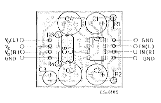
.


.


.


On the other hand, I would recommend, especially for beginners, that you just buy a simple DC adapter (giving about 12V). This is already made and rectified, and most importantly, safe becausemains electricity is dangerous. Get one with a good current output though, I would say 100mA is the absolute minimum, although this amp runs off a 9V PP3 longer than you would expect. For those who want a bit more volume, get a 12V PSU which will provide 1A or more (although more is probably unnecessary), and connect speakers that are sensitive to it, like those elliptical speakers in my radio, or better. Small low cost speakers (especially 55mm or less) have low sensitivity, as do high quality hi-fi speakers and should be avoided unless they are necessary.

This amp can also be very portable, as before I built the radio, I used the amp in a small pair of Walkman type speakers (that were passive). Only from 3V, there was a lot more volume then having them just passive, I recall people were quite impressed (although as you can guess the tone from the speakers was poor). Extra (simple) parts you may want to add to the schematic could be: 3.5mm jack input socket A power switch Batteries 2.1mm power plug (for external PSUs) - if wired correctly, this should disconnect the batteries when a plug is pushed into the socket. Bridge Version There is a bridge variant of this chip available in the datasheet should it be required. It is smaller still then the stereo version of the chip and should provide output levels similar to or even greater then, the TDA7052. .
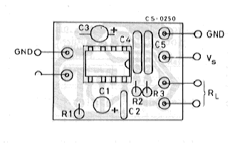
Again, this circuit is simply taken from the datasheet and you may need to modify it to include a single gang volume control. Please refer to the datasheet for schematics, components their values. Thats about all that can be said about this amp because so many applications are possible from it - it is very cheap too, however if you want that extra power, using two TDA7052 amps is also simple and will give you a little more power. Remember that the TDA7052 amplifiers are bridged and may not be suitable for some situations.

Copyright Site design, content and images © Daniel Clarke 2004 Construction made using JHTMLEd - copyright © Daniel Clarke 2004
Article from::: www.electro-dan.co.uk Read More at : http://www.electro-dan.co.uk/electronics/TDA2822.html
ReadMore..

Building with Acrylic


Acrylic Sheeting/Plexiglas:

Acrylic sheeting is widely known as Plexiglas©. Plexiglass©, however, is the name given to acrylic sheeting manufactured by Atofina. The same acrylic type sheeting is also known by the names Acrylite©, Lucite© and Perspex©. From this point on, Ill refer to it simply as acrylic.

Before we go any farther... Do not peel the protective coating from the sheet until the last possible moment. Acrylic sheeting is very easy to scratch. It may be even easier to scratch than CDs.

Cutting Acrylic:
There are a couple of different ways to cut acrylic. Since my experience is mainly with thin acrylic sheeting (1/2" or less), thats what Ill cover.

Table/Circular Saw:
For rough cutting acrylic, you can use a table saw or a circular saw with a fine blade. Blades with fine closely spaced teeth (like those used for plywood) will work relatively well. Blades with widely spaced teeth (like the type used for cutting MDF) will cause a lot more chipping. Ive used an Oldham B7254760 on a circular saw with good results. When using a hand held circular saw, use a guide to make sure you get a straight cut with minimal chipping. There are blades made specifically for cutting acrylic. If youre going to be cutting a lot of acrylic or are using very expensive (thick) material, you need to invest in a blade specifically designed for cutting plastics and laminates.


Jig Saw or Band Saw:
Jig saws can be used to cut acrylic when you need something other than a straight cut. To reduce the work of cleaning up the cut, use the finest blade that you can find. Blades with reduced depth (like those used for scroll work - shown below) will work best due to less friction and less resistance when turning the blade. Youll have to experiment with cutting speed to see what works best. Too much pressure can cause excessive chipping. Going too slow may cause the acrylic to melt. If the acrylic melts when cutting, use a light lubricating oil. Have someone apply the oil to the blade as youre making the cut. DONT use an aerosol dispensed oil. The propellant may be flammable and may be ignited by the jig saw motor. Ive had good results with the blade shown below.


Router:
A router can be used to cut acrylic for either straight or curved cuts. For curved cuts, youll want to use a router with a collar and a guide (pattern or jig made with 1/4 inch plywood). Youll want to rough cut the material within ~1/8 of an inch of the desired finished shape. Trying to cut too much acrylic will lead to melting of the material. Again, youll have to experiment with the speed of the cut. To prevent chipping, make sure the blade is not allowed to break contact with the cut edge. If it does break contact with the material and you push the router blade back into the edge too quickly, the cutter may chip the acrylic. You also must make sure you have a sharp bit (carbide recommended) to prevent melting of the material. Again, youll have to experiment to see what works best for you.


Score and Break:
Thin acrylic sheets (less than ~1/4") can be cut much like regular glass. Instead of using a hardened wheel to chip a line in the glass, youll use a scoring tool to cut a deep scratch in it. The cutting edge of the scoring tool looks something like a single tooth of a table saw blade (but much thinner). You apply pressure to the tool and drag it along a straight edge guide (which should be clamped securely in place to prevent it from moving). You need to continue scoring the acrylic until the cut is ~1/8 of the way through the material (it may take 20 passes on 1/4" thick stock). After thats done, youll have to clamp it down on the edge of a table (or something similar). The edge of the table needs to align with the cut. The edge of the table needs to be perfectly square (a radiused edge on the table wont provide the proper stress along the desired cut line). It needs to be clamped very securely so that it can not flex or move. Youll then apply pressure to the piece thats beyond the edge of the table until it snaps. If it was cut deeply enough, it will break cleanly along the desired line. If it was not cut deeply enough, the cut (on the side opposite the scoring) can be as far outside of the desired cut line as the thickness of the material. The image below shows an inexpensive scoring tool (I think it cost ~$3)


Polishing the Edge of the Cut:
Depending on the quality of the cut and the desired end use, the edge may need to be polished. When using the acrylic as a window on a speaker enclosure or for an amp rack, youll probably want to polish the edge. To make things easy, use a rubber or foam block and waterproof sandpaper. Since it will be nearly impossible to keep the edge perfectly square, Ill usually round it off. With a foam sanding block, start with rough paper (~180 grit). Wet sand with lots of water until the edge is uniform and relatively smooth. Then change to finer and finer paper until you get a satin finish with 600 grit paper (180, 360 and 600 grit will work fine). Remember to use lots of water.

Flame Polishing:
After the edge is polished to a satin finish, you may want to get it to a glass like finish. To do this, you can use a propane torch. Let me recommend that you practice on a scrap piece first. Using a propane torch, you very quickly pass the torch over the edge. You must move the torch very quickly. If you go too slowly, the acrylic will melt and boil. This will leave bubbles in the surface. This is from heating the acrylic too deeply. You only want to heat the very outermost edge/surface to its melting point. This will allow it to flow into a smooth glossy surface. As long as youre moving very quickly along the acrylic, youre not likely to cause bubbles (even if youre using the hottest part of the flame).

Practicing Flame Polishing:
The material that a CD is made of reacts similarly to that of the acrylic sheeting. If you want to scuff up a CD with some 600 grit paper (and water), youll be able to remove most of the finer scratches and haze with the torch. Remember... Move VERY quickly along the surface. Allow the CD to cool between passes with the torch (just as you would when polishing acrylic). Dont you use a good CD. Try it with one that will not play. Heating the CD will cause it to cup slightly and it probably wont play anymore. This exercise is only to allow you too see how the process works. Two final suggestions... Dont burn yourself and dont burn your parents house down.


Drilling Acrylic


Spiral Bit:
Standard spiral drill bits will not work well on acrylic. Their cutting angle is too aggressive which causes it to try to cut too quickly. This will lead to cracking and chipping around the hole. If you want to use a bit that can be used for metal also, try a bit like the one shown in the following photo. You can see that the main cutting edge is flat instead of angled like a normal bit. This causes the material to be cut in a more controlled fashion. If you dont want to spend the money on a new bit, you can grind a regular bit to the same profile.


Forstner Bit:
Forstner bits are very high quality bits that are generally used for woodworking. They make a very clean hole with little or no chipping. When used for drilling acrylic, you may need to use a cutting lubricant. I generally use a 3 in 1 type oil. Apply the oil to the cutting surface prior to drilling and to the drill bit shaft as youre moving through the material. If the bit is used dry, the friction between the sides of the bit and the material will cause the acrylic to melt (very bad). When used with lubricant, the hole will be very clean.


Standard Woodboring Bit:
Some people recommend against using woodboring bits but Ive never had a problem with them. One advantage of the wood bit is the long centering point. This point will exit the other side of the material before the cutting edge. This allows you to turn the material over and drill from the other side. Since the cutting edge will not be pushing out as the bit cuts through surface of the material, there will be little or no chipping on either side of the material.


When using any of the different bits for drilling acrylic, you should:
  • Go slow. Do not force the bit to cut too quickly.
  • Use a drill press. This allows you to have much more control over the cutting speed and assures that youre drilling the hole perfectly perpendicular to the material. You should clamp small pieces down. If the bit grabs the material and spins it, it will cut you. Small pieces dont allow you to get a good enough grip to prevent the piece from spinning with the bit.
  • Practice on a piece of scrap material. If you crack a piece of acrylic after youve already polished the edges, you are not going to be happy.
  • If the acrylic melts as you drill through it (regardless of rate of rotation/feed), try using a light lubricating oil to reduce friction between the bit and the acrylic.

    Fasteners:
    When screwing a piece of acrylic down, youll need to use some type of washer under the screw. Fiber, plastic and rubber washers will work. If you cant find those types of washers, standard metal flat washers will be better than nothing. If you use washers, youre less likely to crack the material if the screw doesnt go in prefectly straight. Predrilling the hole in the wood will help assure that the screw goes in straight. When tightening the screws, do not overtighten (especially when the surface under the acrylic is not hard). If theres a soft gasket under the acrylic, overtightening the screw will cause the material to crack. You should also use pan head screws (those with a flat mating surface under its head). Using bevel or bugle headed (drywall) screws will cause the acrylic to crack
ReadMore..

Build a Digital Theremin Wiring diagram Schematic

Theremin schema shown in this schematic diagram uses digital component, so we can call it a digital Theremin. This schema employs  logic inverter 74C04 or CD4069 hex inverter and CD4046 phase-locked-loop (PLL) IC. 

The CD4069 logic inverter is operated as a fixed-frequency oscillator with  frequency around 100kHz. The CD4046 is operated as a variable frequency oscillator which is adjustable around 100kHz. The exact center frequency of the on-chip oscillator is determined by R4, C2 and R3. Here is the schematic diagram of the schema. 

Digital Theremin Circuit Diagram


The frequency of variable oscillator frequency schema can be shifted several kilohertz by moving your hand approaching the antenna since the C2 and the antenna form an equivalent parallel capacitance. The frequency of the variable oscillator should be set to the same frequency of fixed oscillator when there is no hand or human body close to the antenna. 

This  calibration is done by adjusting the  zero control R4 pot with this simple rule: If  both oscillators (the fixed and the variable) are set to the same frequency then the Theremin will produce no output (silent). This Theremin schema will start  producing audible tone if you move your hand approaching the antenna since it will shift the frequency of the variable oscillator. You can play this Theremin schema by moving your right hand around the antenna and at the same time turning the volume knob R5 with your left hand.
ReadMore..

Solar Tracking System Wiring diagram Schematic

Generally, solar panels are stationary and do not follow the movement of the sun. Here is a solar tracker system that tracks the sun’s movement across the sky and tries to maintain the solar panel perpendicular to the sun’s rays, ensuring that the maximum amount of sunlight is incident on the panel throughout the day. The solar tracker starts following the sun right from dawn, throughout the day till evening, and starts all over again from the dawn next day.

Solar
Fig. 1: Circuit of solar tracking system

Fig. 1 shows the schema of the solar tracking system. The solar tracker comprises comparator IC LM339, H-bridge motor driver IC L293D (IC2) and a few discrete components. Light-dependent resistors LDR1 through LDR4 are used as sensors to detect the panel’s position relative to the sun. These provide the signal to motor driver IC2 to move the solar panel in the sun’s direction. LDR1 and LDR2 are fixed at the edges of the solar panel along the X axis, and connected to comparators A1 and A2, respectively. Presets VR1 and VR2 are set to get low comparator output at pins 2 and 1 of comparators A1 and A2, respectively, so as to stop motor M1 when the sun’s rays are perpendicular to the solar panel.

When LDR2 receives more light than LDR1, it offers lower resistance than LDR1, providing a high input to comparators A1 and A2 at pins 4 and 7, respectively. As a result, output pin 1 of comparator A2 goes high to rotate motor M1 in one direction (say, anti-clockwise) and turn the solar panel.

When LDR1 receives more light than LDR2, it offers lower resistance than LDR2, giving a low input to comparators A1 and A2 at pins 4 and 7, respectively. As the voltage at pin 5 of comparator A1 is now higher than the voltage at its pin 4, its output pin 2 goes high. As a result, motor M1 rotates in the opposite direction (say, clock-wise) and the solar panel turns.


Fig. 2 Proposed assembly for the solar tracking system

Similarly, LDR3 and LDR4 track the sun along Y axis. Fig. 2 shows the proposed assembly for the solar tracking system.

ReadMore..

Nicad Battery charger include voltage limiting

In this my circuit , which is one of a series of simple battery charger , but this circuit to charger the Nicad battery . This circuit included with current and voltage limting . Why use it ?? because with current voltage you can choose voltage to charge a battery , and the limiting voltage use limit voltage if the battery is fully, because if battery fully that damaged quickly.

See this schematic below :


Click to view Enlarge


Lamp 1 will glow brightly and the LED will be out when the battery is low or run out and the circuit is processing being to charged , but the LED will bright and the light dim when the battery is almost ready. Output voltage between 12 to 14 volt with current 100 mA.
ReadMore..

TA8210AH Audio Amplifier 2x22W

TA8210AH general description:

     Its amizing circuit work beautiful. Is desination for audio amplification, for car. This is a circuit of 2 x 22 watt BTL amplifier using IC TA8210AH. It is not only an auto amplifier, ideal for a low-frequency auditory approach those hi-fi, with a very good linear feature. Can be fueled by a 12 volt car battery but shi from a 12 volt charger. The chip incorporates four bridge amplifiers available in two by two in order to ensure the output 22 watts per channel on 4 ohms. TA8210AH Audio Amplifier 2x22W

TA8210AH features:
  • Peak supply voltage (0.2s): 50 V
  • supply voltage VCC (DC): 25 V
  • Operating supply voltage VCC (opr): 18 V
  • Output current (peak): 9 A
  • Power dissipation PD: 50 W
  • Operating temperature: 30~85 °C
  • Storage temperature: 55~150 °C

TA8210AH circuit diagram:


TA8210AH layout:


ReadMore..

Wednesday, September 17, 2014

Arduino Based Capacitive Touch Screen

Arduino based projects are quite complicated and is no cake walk for beginners in this field. Interfacing a tablet with the microcontroller is a daunting task. Let see how its done here.


Hacks
The primary focus should be on using the appropriate drivers for the tablet. This makes it a USB host. As seen in the video, light can be a medium of communication between the tablet and the microcontroller. A photo diode or photoresistor is what is needed here and this should be pressed against the Lcd.

Building a touch sensing capability can help in providing communication between the microcontroller and the tablet. Capacitive touch Lcds function by sensing the capacitance changes on the Lcd. In this case, a large conductive brass plate is used to simulate touch. The surface area of the conductor used here to simulate the touch sould be large.

Testing can be done by touching the scrren with a wire and holding the other end. This may not work. This is made to work by sticking a piece of aluminum foil on to the Lcd and connecting the free end to the pin that is available on the arduino. The video shows the working of the capacitive touch Lcd. The setup is quite fragile and a little more schemary could improve its reliability. Thus the capacitive touch Lcd is done.
ReadMore..

Fuse Box Ford 2003 Crown Victoria Diagram

Fuse Box Ford 2003 Crown Victoria Diagram - Here are new post for Fuse Box Ford 2003 Crown Victoria Diagram.

Fuse Box Ford 2003 Crown Victoria Diagram


Fuse
Fuse

Fuse Panel Layout Diagram Parts: subwoofer amplifier, trailer exterior lamp relay, horn relay, lighting control module, air suspension compressor relay, air spring solenoid, Starter relay, head lamp, starter relay, generator, radio amplifier, police power relay, daytime running lamp, PCM power relay, cooling fan relay, rear window defrost relay, trailer turn, battery charging relay, police option fuse holder, electric fuel pump relay, anti lock brake module, electric brake controller, power door lock, power seat, trunk lid release, fuel filler door releas.
ReadMore..