Showing posts with label circuit. Show all posts

Tuesday, January 6, 2015

Electronic Timer with display circuit

timer-circuit

Using this electronic scheme can be built an electronic timer which can be set to measure a maximum of 60 hours. 

The electronic timer allows the fixation of some intermediate time. On reaching this point, a buzzer will sound. 

The circuit is built using ICM7217 integrated circuit, manufactured by Intersil, which contains a CMOS counter up / down, with 4 digits and display properly. 
ReadMore..

Thursday, December 11, 2014

Alarm Circuit

  1. A Transistor Based of Single Zone Alarm - If the building is not secure, when you switch the alarm on the buzzer will sound.
  2. Hijack Alarm - This circuit is designed primarily for the situation where a hijacker forces the driver from the vehicle. If a door is opened while the ignition is switched on, the circuit will trip.
  3. Car Alarm and Immobilizer - This circuit features exit and entry delays, an instant alarm zone, an intermittent siren output and automatic reset.
  4. Single Zone CMOS Alarm - This circuit has provision for normally open and normally closed switches and will accommodate the usual input devices such as Foil Tape, Pressure Mats, Magnetic Reed Contacts, Passive Infrared Detectors and Inertia (Shock) Sensors.
ReadMore..

Thursday, November 20, 2014

Flip Flop Led Circuit

Flip Flop LED
Flip flop circuit is a series of free runing multivibrator given the burden of LEDs on each side of the transition changes its output signal. Flip flop circuit with LEDs is quite simple, that is prepared with 2 units and 2 units of 2N3904 transistor circuit tank circuit composed by the RC circuit. 
LED indicators signal a change that is placed on each side of the flip flop will be lit in turn by the fire and extinguished the same as the charge and discharge capacitor. Flip flop circuit is quite simple as shown in the picture below.

Flip Flop LED series

The working principle is the flip flop over when the series voltage source is given then the 10uF capacitor will be charged through R 470 and the LED will then be forwarded to triger the transistor base so that the transistor will turn ON and LEDs. this occurs alternately on each side, so that the LED light will illuminate in turn as well.
ReadMore..

Wednesday, November 19, 2014

Audio Surround Decoder Circuit

The circuit schematic drawings Surround Audio Decoder and its components and how to make it ,Audio surround decoder circuit. Surround sound quality is the process of adding the audio source by increasing the number of speakers. This is done by producing audio multitracking in a way that can be issued on a multichannel speaker.


Basically surround adopt an existing stereo system. The system uses a two-speaker stereo is right speaker and left speaker. With two speakers will be three-dimensional effect of the sound issued. With the surround, which generated three-dimensional effect was more extensive than in stereo. This is because the surround speakers that use more than two pieces. In addition to supporting the three-dimensional effects, stereo field theory is also noteworthy to organize the arrangement of sounds based on the type of sound produced.

Component List :

R1-2-7-8-12-13-18-19-20 : 47Kohm
R3-4-5-6-21-22-34-35    : 10Kohm
R9-10-11-14-15-16-17    : 15Kohm
R23-24-25-33-36         : 100ohm
R26-27-28-31-32         : 100Kohm
R29-30                  : 5.6Kohm
C1-8                    : 47uF/25V
C2-7-9-14-23            : 47nF
C3-6                    : 1uF/100V
C4-5-10                 : 33pF
C11-12-15               : 10uF/25V
C13                     : 82nF
C16                     : 18pF
C17                     : 100pF mini adjustable capacitor
C18                     : 2.2nF
C19                     : 4.7uF/25V
C20                     : 100nF
C21                     : 10nF
C22                     : 180pF
C24                     : 150nF
RV1-RV2                 : 2 X 10Kohm  Log. pot.
RV3-4                   : 10K Log pot.
D1                      : 1N4148
IC1-6                   : TL072
IC2-3                   : TL074
IC4                     : MN3101
IC5                     : MN3004


Surround effects can only be listened to speakers who have more than two channels. Surround is a technique commonly used in todays films that utilize multichannel speakers. Surround allows voice can move from side to side, is a moving side to side is to move from one speaker to another speaker. To create three-dimensional sound effects you can use a series of audio surround decoder.
ReadMore..

Audio phase shift oscillator Circuit Diagram

Here is a phase-shift audio oscillator with excellent distortion characteristics thanks to “softened” diode limiting provided by the 1N914 and resistor divider and degenerated gain provided by the 68 ohm emitter resistor. For minimum distortion, increase the 68 ohm resistor to a point just below where oscillation stops. A simple buffer may be added for driving lower impedance loads.


The output amplitude will be about 5 volts p-p but one of the 1N914’s 10k divider resistors may be changed for a different output amplitude. The circuit will work well with a power supply voltage other than 9 volts but the 68 ohm resistor may need adjustment
ReadMore..

Tuesday, November 18, 2014

DC Motor Controller Circuit with NE555


A simple DC motor controller circuit with NE555 is shown here. several DC motor speed control circuits are revealed here however this can be the first one using NE555 timer IC. additionally to controlling the motors speed its direction of rotation will be also modified using this circuit.

A PWM circuit primarily based on timer NE555 is that the heart of this circuit. NE555 is wired as an astable multivibrator whose duty cycle will be adjusted by varying the POT R1. The output of IC1 is coupled to the base of transistor Q1 that drives the motor according to the PWM signal available at its base. Higher the duty cycle the typical voltage across motor will be high which ends in higher motor speed and vice versa. modification of DC motor direction is attained using the DPDT switch S1 that on application simply toggles the polarity applied to the motor.
ReadMore..

Monday, November 17, 2014

FM Transmitter circuit using 2N2222


The FM transmitter circuit is using NPN transistor 2N2222. The L1 and C1 producess necessary oscillations Q1.The collector capacity C4, R3 and R4 resistor performs the function of the output mix theaudio to stereo player or i-emitter resistor R2 Pod.The provides sufficient stability for circuit.It also limits the collector current increse the battery.

With this circuit compact FM adapter connected to the audio output of your cassette player or i pod words, you can listen to your favorite music on the car track is stereo.This doesnot handy if your car stereo has an auxiliary circuit outlet is not to buy a short-range FM transimitter.
ReadMore..

Circuit Mobile Phone Battery Charger

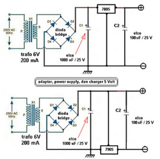
This post share about Mobile Phone charger circuits, previously you can see other Phone Battery Charger Circuit  or Charger Circuit . This Charger ciruit use to charging phone battery using IC 7805 for plus voltage regulator or & 7905 for min voltage regulator. Below is a schematic circuit adapter, power supply, or battery charger (for gadgets, mobile phones, MP4player, smartphone) that is equipped with a 5V voltage stabilizer:

adapter

Diode Bridge
diode bridge, known as a diode bridge is used for the rectifier circuit current (rectifier) from AC to DC. to make the diode bridge properly you need to know the type of diode to be used, to suit your needs. example: to make the power supply 12 Volt 3 ​​Ampere diode type 1N5401 is needed, for more detail how to choose the right type of diode to the adapter.

Voltage stabilizers are commonly used are the 78XX or 79XX type LM, XX indicates the maximum voltage output is generated. see the example in the circuit schematic above, to output 5 V is used type LM 7805. for other voltages must be adjusted to the transformer and its stabilizer IC.

ReadMore..

Saturday, November 15, 2014

How to Build a Common-Emitter Proximity Detector

A proximity detector is gagdet that detects when an object is nearby. There are 2 ways to build a protximity detector. One is mount the IR LED and the phototransistor so that they face each other. Then the infrared light is detected by the phototransistor. If an object comes between the IR LED and the phototransistor, the light is blocked, and the phototransistor turns off.

The other way is to build a proximity detector is to mount the IR LED and the IR photodiode next to each other facing the same direction. When an object comes near the IR LED, some infrared light will bounce off the object and be detected by the phototransistor.

How to Build a Common-Emitter Proximity Detector

Parts
Phototransistor
33KΩ Resistor
330Ω Resistor
IR LED
9-volt Battery or DC Power Supply
Red LED

Schematic Diagram
Proximity Detector Circuit

ReadMore..

Friday, November 14, 2014

MOBILE PHONE JAMMER CIRCUIT

Circuit showing a mobile phone jammer. A FM transistor is used for making this circuit. Mobile phones are working in 450 MHz frequency. Here the transmitter generate almost equal to 450 MHz frequency, therefore the mobile phone does not identify the original signal. But the signal range is very week, so this circuit working in only 100 m range. This circuit working in only 450 Mhz . Do not give more than 3 V.

For any jammer circuit, remember that there are three main important circuits. When they are combined together, the output of that circuit will work as a jammer. The three circuits are
  • RF amplifier.
  • Voltage controlled oscillator.
  • Tuning circuit.

Circuit Diagram


Parts List 

ComponentsValue  Usage
R1         100R   Emitter loading
R2         39k    Base Biasing
C1         15 pf Frequency Generating
C2         4.7pf Feedback
C3         4.7pf Feedback
C4         102pf Noise Reduce
C5         1uF    Coupling
C6         2.2pf Coupling
C7         103pf  Decoupling 
Q1         BF 494 Amplification
L1         22nH   Frequency Generating
ReadMore..

AM RECIEVER CIRCUIT

It can use general purpose transistors, and in this example there are 3 BC109C transistors. The schematic and BOM show a 200µH inductor and a trimmer capacitor 150-500pF, though these parts can be salvaged from an old AM radio, to preserve the directional nature of a tuning coil, and an adjustment knob (plate capacitor) that work well for radio reception.
 
The 120k resistor is for regenerative feedback between the Q2 NPN transistor and the input to the tank circuit. The value of this resistor is important to the performance of the entire AM receiver. In fact, it may be better to replace the fixed value with a variable resistor paired with a fixed resistor to adjust the oscillation and sensitivity. All the connections should be short to minimize interference.

Performance will vary depending on stray capacitance in your layout, the inductor winding/core/length, etc. Changing values of some of the capacitors, or adding them, as well as a potentiometer in the feedback loop can help with the performance of the receiver. With such a small circuit that is affected so much by its construction and its environment, a lot of hand tuning and experimentation will be fun, instructive, and possibly necessary to make it work best.

Circuit Diagram


Parts List

Symbol                     Name                                        Value
C1              VARIABLE                500pF
C2              NON POLARIZED           0.1uF
L1              AIR CORE                200uH
Q1              NPN
Q2              NPN
Q3              NPN
R2              RESISTOR                1K
R3              RESISTOR                330K
C3              NON POLARIZED           0.1uF
R1              RESISTOR
R4              RESISTOR                560K
R5              RESISTOR                10K
C4              NON POLARIZED           0.1uF

Application

A small, simple AM receiver project with only 3 transistors. This circuit can pick up medium wave stations in your area.

ReadMore..

IC 74hc14 Arrow led indicator circuit with explanation


This arrow led indicator electronic project can be used in some dark places to show the directions . You can use to indicate direction just an illuminated arrow or a flashing light , but is much nicer if the light moves in the correct direction.
This arrow led indicator is based on 74HC14 circuit and some LEDs which are used to show the way .

For this arrow led indicator we need six series of three LEDs arranged in the shape of arrows and are connected to the outputs . Each time the lit arrows move over by one column so it appears that the arrows run from right to left.
If we want to change the speed of the moving light it’s need to change the value of C1 to C3 or R1 to R3 ( a lower value for this components decrease the time of moving lights) .
If we want a longer arrow we can mount in parallel with existing columns another columns .
For power supply we can use batteries or 6V regulated power supply .

ReadMore..

Thursday, November 13, 2014

Water Sensor Circuit Diagram using IC 555

This is a water sensor /rain alarm circuit diagram; it can be used on motorcycle, car or other device that we want to protect from water, rain.
This is a simple water sensor/rain alarm circuit that makes an alarm when water/rain falls on its sensor. This circuit is based on NE555/LM555 IC and two transistors (Q1&Q2). For  transistor Q1- BC547 or BC107 and for Q2-  2N825,BC548 or BC168 can be used in the circuit. This rain detector circuit can be supplied from voltage source of +9V-12V DC. The resistor 470K ohm is a POT/Variable resistor; it is used to adjust the sensitivity of water/rain sensor. Use a 8 ohm,0.5w-1W  speaker to hearing  better alarm. Less than 8 ohm speaker could be harmful for the IC 555.

Circuit Diagram of Water Sensor

Fig-1: Water Sensor/Rain alarm circuit diagram

Water sensor PCB layout:

Fig-2: PCB layout of water sensor
We can make the water sensor as shown in the image (Fig-2) using aluminum conductor like a naked wire . Here can be used other conductor but we suggesting to use aluminum.
ReadMore..

LM317 Circuit

Introduction
The LM317 is AN adjustable three terminal transformer that is capable of supply 1.2 to 37 volts with a secure 1.5A output current. The LM317 is prepackaged terribly} normal electronic transistor package that makes it very simple to mount in your circuits. 
Schematic


Overview
The LM317 series of adjustable 3-terminal positive voltage regulators is capable of supply in more than 1.5A over a 1.2V to 37V output vary. theyre exceptionally simple to use and need solely 2 external resistors to line the output voltage. Further, each line and cargo regulation square measure higher than normal mounted regulators.

In addition to higher performance than mounted regulators, the LM317 series offers full overload protection out there solely in ICs. enclosed on the chip square measure current limit, thermal overload protection and safe space protection.

The LM317 makes AN particularly easy adjustable change regulator, a programmable output regulator, or by connecting a set electrical device between the adjustment pin and output, the LM317 may be used as a preciseness current regulator. provides with electronic conclusion may be achieved by clamping the adjustment terminal to ground that programs the output to one.2V wherever most masses draw very little current.

Pinout

Options


Specifications

  • Guaranteed 1% output voltage tolerance (LM317A)
  • Guaranteed max. 0.01%/V line regulation (LM317A)
  • Guaranteed max. 0.3% load regulation (LM117)
  • Guaranteed 1.5A output current
  • Adjustable output down to 1.2V
  • Current limit constant with temperature
  • P + Product Enhancement tested
  • 80 dB ripple rejection
  • Output is short-circuit protected
Output Formula
ReadMore..

60 Watt Guitar Amplifier Diagram Circuit

This design adopts a well established circuit topology for the power amplifier, using a single-rail supply of about 60V and capacitor-coupling for the speaker(s). The advantages for a guitar amplifier are the very simple circuitry, even for comparatively high power outputs, and a certain built-in degree of loudspeaker protection, due to capacitor C8, preventing the voltage supply to be conveyed into loudspeakers in case of output transistors failure. The preamp is powered by the same 60V rails as the power amplifier, allowing to implement a two-transistors gain-block capable of delivering about 20V RMS output. This provides a very high input overload capability.Amplifier circuit diagram:
60 Watt Guitar Amplifier Circuit Diagram
Amplifier parts:R1__________________6K8 1W Resistor
R2,R4_____________470R 1/4W Resistors
R3__________________2K 1/2W Trimmer Cermet
R5,R6_______________4K7 1/2W Resistors
R7________________220R 1/2W Resistor
R8__________________2K2 1/2W Resistor
R9_________________50K 1/2W Trimmer Cermet
R10________________68K 1/4W Resistor
R11,R12______________R47 4W Wirewound Resistors
C1,C2,C4,C5________47µF 63V Electrolytic Capacitors
C3________________100µF 25V Electrolytic Capacitor
C6_________________33pF 63V Ceramic Capacitor
C7_______________1000µF 50V Electrolytic Capacitor
C8_______________2200µF 63V Electrolytic Capacitor (See Notes)
D1_________________LED Any type and color
D2________Diode bridge 200V 6A
Q1,Q2____________BD139 80V 1.5A NPN Transistors
Q3_____________MJ11016 120V 30A NPN Darlington Transistor (See Notes)
Q4_____________MJ11015 120V 30A PNP Darlington Transistor (See Notes)
SW1_______________SPST Mains switch
F1__________________4A Fuse with socket
T1________________220V Primary, 48-50V Secondary 75 to 150VA Mains transformer (See Notes)
PL1_______________Male Mains plug
SPKR______________One or more speakers wired in series or in parallel Total resulting impedance: 8 or 4 Ohm Minimum power handling: 75W

Preamplifier circuit diagram:
Guitar Preamplifier Circuit Diagram
Preamplifier parts:P1,P2______________10K Linear Potentiometers
P3_________________10K Log. Potentiometer
R1,R2______________68K 1/4W Resistors
R3________________680K 1/4W Resistor
R4________________220K 1/4W Resistor
R5_________________33K 1/4W Resistor
R6,R16______________2K2 1/4W Resistors
R7__________________5K6 1/4W Resistor
R8,R21____________330R 1/4W Resistors
R9_________________47K 1/4W Resistor
R10_______________470R 1/4W Resistor
R11_________________4K7 1/4W Resistor
R12,R20____________10K 1/4W Resistors
R13_______________100R 1/4W Resistor
R14,R15____________47R 1/4W Resistors
R17,R18,R19_______100K 1/4W Resistors
C1,C4,C5,C6________10µF 63V Electrolytic Capacitors
C2_________________47µF 63V Electrolytic Capacitor
C3_________________47pF 63V Ceramic Capacitor
C7_________________15nF 63V Polyester Capacitor
C8_________________22nF 63V Polyester Capacitor
C9________________470nF 63V Polyester Capacitor
C10,C11,C12________10µF 63V Electrolytic Capacitors
C13_______________220µF 63V Electrolytic Capacitor
D1,D2____________BAT46 100V 150mA Schottky-barrier Diodes (see Notes)
Q1,Q3____________BC546 65V 100mA NPN Transistors
Q2_______________BC556 65V 100mA PNP Transistor
J1,J2___________6.3mm. Mono Jack sockets
SW1,SW2___________SPST SwitchesSensitivity:
35mV input for 40W 8 Ohm output
42mV input for 60W 4 Ohm output
Frequency response:
50Hz to 20KHz -0.5dB; -1.5dB @ 40Hz; -3.5dB @ 30Hz
Total harmonic distortion @ 1KHz and 8 Ohm load:
Below 0.1% up to 10W; 0.2% @ 30W
Total harmonic distortion @ 10KHz and 8 Ohm load:
Below 0.15% up to 10W; 0.3% @ 30W
Total harmonic distortion @ 1KHz and 4 Ohm load:
Below 0.18% up to 10W; 0.4% @ 60W
Total harmonic distortion @ 10KHz and 4 Ohm load:
Below 0.3% up to 10W; 0.6% @ 60W
Treble control:
+9/-16dB @ 1KHz; +12/-24dB @ 10KHz
Brightness control:
+6.5dB @ 500Hz; +7dB @ 1KHz; +8.5dB @ 10KHz
Bass control:
-17.5dB @ 100Hz; -26dB @ 50Hz; -28dB @ 40HzNotes:
  • The value listed for C8 is the minimum suggested value. A 3300µF capacitor or two 2200µF capacitors wired in parallel would be a better choice.
  • The Darlington transistor types listed could be too oversized for such a design. You can substitute them with MJ11014 (Q3) and MJ11013 (Q4) or TIP142 (Q3) and TIP147 (Q4).
  • T1 transformer can be also a 24 + 24V or 25 + 25V type (i.e. 48V or 50V center tapped). Obviously, the center-tap must be left unconnected.
  • D1 and D2 can be any Schottky-barrier diode types. With these devices, the harmonic modifier operation will be hard. Using for D1 and D2 two common 1N4148 silicon diodes, the harmonic modifier operation will be softer.
  • In all cases where Darlington transistors are used as the output devices it is essential that the sensing transistor (Q2) should be in as close thermal contact with the output transistors as possible. Therefore a TO126-case transistor type was chosen for easy bolting on the heatsink, very close to the output pair.
  • R9 must be trimmed in order to measure about half the voltage supply across the positive lead of C7 and ground. A better setting can be done using an oscilloscope, in order to obtain a symmetrical clipping of the output wave form at maximum output power.
  • To set quiescent current, remove temporarily the Fuse F1 and insert the probes of an Avo-meter in the two leads of the fuse holder.
  • Set the volume control to the minimum and Trimmer R3 to its minimum resistance.
  • Power-on the circuit and adjust R3 to read a current drawing of about 30 to 35mA.
  • Wait about 15 minutes, watch if the current is varying and readjust if necessary.
Author: www.redcircuits.com
ReadMore..

Heat Sensor Circuit Diagram

This simple heat sensor circuit could senses heat from various electronics device like computer, amplifier etc. and generate warning alarm. It could senses heat from environment also, but here I mention “electronics device” because it is being using mostly in electronic device to protect them from overheat.

Circuit diagram of heat sensor:

Heat
Fig-1: Schematic Circuit Diagram Of Heat/Temperature Sensor


Thermistor, 110 Ohms:

Thermistor
Fig-2: 110 Ohms Thermistor
As it is a heat sensor circuit, here a thermistor is used as a heat sensor. It is a thermal measurement device and has a variety of usages including temperature sensor/ heat sensor. The thermistor used in this circuit is a NTC (Negative Temperature Coefficient) type thermistor. When temperature increases, its resistance goes decrease. Therefore, NTC thermistor’s resistances are inverse of temperature.

Circuit Description:

You have seen, in this simple circuit diagram of heat sensor, a few number of components is used including a BC548 transistor, a 110 ohms thermistor etc.
  • BC548: BC548 is a TO-92 type NPN transistor, as its alternative you can use 2N2222, BC238, BC548, BC168, BC183 etc. they all have almost same characteristic.
  • 110 Ohms Thermistor: A 110 Ohms thermistor is used to detecting heat. I have told already about it.
  • Buzzer: A buzzer is used with +9V and collector of transistor. When the temperature/ heat exceeds a certain level then it make an alarm.
  • 4.7V Zener diode:  It is used to limit the emitter current of BC548.
  • 9V Battery: A 9V battery is used as a single power source.
  • R1, R2: A 3.3K 1/4w resistor is used as R1 and 100 ohms 1/4w as R2.
  • Switch: Here in this circuit the switch used is a simple SPST switch. You can either use the switch or not, choice is yours. It is not mandatory.
ReadMore..

Saturday, November 1, 2014

Ampere or Current Booster Circuit

Volt regulators such as the LM708, and LM317 series (and others) sometimes need to provide a little bit more current then they actually can handle. If that is the case, this little circuit can help out. A power transistor such as the 2N3772 or similar can be used.
The power transistor is used to boost the extra needed current above the maximum allowable current provided via the regulator.
Current up to 1500mA(1.5amp) will flow through the regulator, anything above that makes the regulator conduct and adding the extra needed current to the output load. It is no problem stacking power transistors for even more current. (see diagram). Both regulator and power transistor must be mounted on an adequate heatsink.


Circuit diagram:


Ampere or Current Booster Circuit Diagram


Parts:

R1 = 1R-2W
R2 = 10R-2W
C1 = 35v-470uF
C2 = 35v-470uF
Q1 = TIP2955
IC1 = 78xx Regulator
ReadMore..

Friday, October 31, 2014

Balancing LiPo Cells Circuit Diagram

Things change fast in the electronics world, and that’s also true for recharge- able batteries. The rate of development of new types of rechargeable batteries has been accelerated by the steadily increasing miniaturisation of electronic equipment. LiPo cells have conquered the market in a relatively short time. Their price and availability have now reached a level that makes them attractive for use in DIY circuits.

Balancing LiPo Cells Circuit diagram

BalancingBalancing LiPo Cells Circuit diagram

Unlike its competitors Elektor Electronics has already published several articles about the advantages and disadvantages of LiPo batteries. One of the somewhat less well-known properties of this type of rechargeable battery is that the cells must be regularly ‘balanced’ if they are connected in series. This is because no two cells are exactly the same, and they may not all have the same temperature. For instance, consider a battery consisting of a block of three cells. In this case the outer cells will cool faster than the cell in the middle. Over the long term, the net result is that the cells will have different charge states. It is thus certainly possible for an individual cell to be excessively discharged even when the total voltage gives the impression that the battery is not fully discharged. That requires action – if only to prolong the useful life of the battery, since LiPo batteries are still not all that inexpensive. 

One way to ensure that all of the cells have approximately the same charge state is limit the voltage of each cell to 4.1 V during charging. Most chargers switch over to a constant voltage when the voltage across the batter terminals is 4.2 V per cell. If we instead ensure that the maximum voltage of each cell is 4.1 V, the charger can always operate in constant-current mode. 

When the voltage of a particular cell reaches 4.1 V, that cell can be discharged until its voltage is a bit less than 4.1 V. After a short while, all of the cells will have a voltage of 4.1 V, with each cell thus having approximately the same amount of charge. That means that the battery pack has been rebalanced. 

The circuit (Figure 1) uses an IC that is actually designed for monitoring the supply voltage of a microcontroller circuit. The IC (IC1) normally ensures that the microcontroller receives an active-high reset signal whenever the supply voltage drops below 4.1 V. By contrast, the out-put goes low when the voltage is 4.1 V or higher. In this circuit the output is used to discharge a LiPo cell as soon as the voltage rises above 4.1 V. 

When that happens, the push-pull output of IC1 goes low, which in turn causes transistor T1 to con-duct. A current of approximately 1 A then flows via resistor R1. LED D2 will also shine as a sign that the cell has reached a voltage of 4.1 V. The function of IC2 requires a bit of explanation. The circuit built around the four NAND gates extends the ‘low’ interval of the signal generated by IC1. That acts as a sort of hysteresis, in order to prevent IC1 from immediately switching off again when the voltage drops due the internal resistance of the cell and the resistance of the wiring between the cell and the circuit. The circuitry around IC2 extends the duration of the discharge pulse to at least 1 s.
Balancing


Figure 2 shows how several circuits of this type can be connected to a LiPo battery. Such batteries usually have a connector for a balancing device. If a suit-able connector is not available, you will have to open the battery pack and make your own connections for it. The figure also clearly shows that a separate circuit is necessary for each cell.
ReadMore..

Alarm LED Light Circuit

This circuit yearn for act the performance of the equipment,otherwise Check the fuse here the circuit.The circuit is diminutive and the power supply voltage of all kinds. It demonstrate with LED, 2-color in individual. Which is cathode universal kind,the anode has two separate terminals. If the circuit is functioning well LED, it revealed in wet behind the ears colour.The display is red, as the fuse into the circuit is damaged.The resistor R1 limits the current to gush through the LED is roughly 2 mA.This is an adequate amount to produce the LED light.If it lowers the R1 down, the LED light up.

Alarm
Alarm LED Light Circuit Diagram

In the conventional setup of the circuit and The fuse is not damaged. The zener diode to prevent the green and red LED illumination up in chorus.Zener diode prevents the LED is simple and red illumination all together.
The piercing efficiency LED, as soon as connected trendy like. The red LED uses high-pressure, so with the intention of single green LED illumination up only. Diodes D3 and D4 wish prevent dodgy instead of the LED. While the semi cycle downbeat voltage of the alternating current voltage.However, if the DC supply voltage.I act not retain to manage diode protection.

ReadMore..

Automatic Fan Controller Circuit Diagram

This circuit will turn on/off 12V DC fan or CPU fan when temperature above normal temperature.You can set turn on temperature by adjust VR1. This circuit use an NTC (Negative temperature coefficient)which is a thermistor is one in which the zero-power resistance decreases with an increase in temperature. So If temperature increate the voltage at pin 3 on LM311 will decreated .The resistance of NTC is about 10K at 25c.

VR1 should be multi-turn potentiometer type such 10K/25 turn
ReadMore..