Showing posts with label detector. Show all posts

Friday, December 12, 2014

Lie detector schematic diagram


It's a simple lie detector that can be built in a few minutes, but can be incredibly useful when you want to know if someone is really telling you the truth. It is not as sophisticated as the ones the professionals use, but it works. It works by measuring skin resistance, which goes down when you lie.
ReadMore..

Phone calling Detector

phone-schematic-diagram


This circuit was designed to detect when a call is incoming in a cellular phone (even when the calling tone of the device is switched-off) by means of a flashing LED.The device must be placed a few centimeters from the cellular phone, so its sensor coil L1 can detect the field emitted by the phone receiver during an incoming call.
ReadMore..

Saturday, November 15, 2014

How to Build a Common-Emitter Proximity Detector

A proximity detector is gagdet that detects when an object is nearby. There are 2 ways to build a protximity detector. One is mount the IR LED and the phototransistor so that they face each other. Then the infrared light is detected by the phototransistor. If an object comes between the IR LED and the phototransistor, the light is blocked, and the phototransistor turns off.

The other way is to build a proximity detector is to mount the IR LED and the IR photodiode next to each other facing the same direction. When an object comes near the IR LED, some infrared light will bounce off the object and be detected by the phototransistor.

How to Build a Common-Emitter Proximity Detector

Parts
Phototransistor
33KΩ Resistor
330Ω Resistor
IR LED
9-volt Battery or DC Power Supply
Red LED

Schematic Diagram
Proximity Detector Circuit

ReadMore..

Friday, October 31, 2014

Best Performance Interruption Detector Schematic

Best Performance Interruption Detector Schematic Circuit, The circuit presented here detects interruption in security systems. Its features include no false triggering by external factors (such as sun-light and rain), easy relative positioning of the sensors and alignment of the circuit, high sensitivity, and reliability. The circuit comprises three sections, namely, transmitter, receiver, and power supply. The transmitter generates modulated IR signals and the receiver detects the change in IR intensity. Power supply provides regulated +5V to the transmitter and the receiver. 

The power supply and the speaker are kept inside the premises while the transmitter and the receiver are placed oppo site to each other at the entrance where the detection is needed. Three connections (Vcc, GND, and SPKR) are needed from the power supply/speaker to the receiver section, while only two connections (Vcc and GND) are required to the transmitter. The transmitter is basically an astable multivibrator configured around NE555 (IC3). Its frequency should match the frequency of the detector/sensor module (36 kHz for the module shown in figure) in the receiver. The transmitter frequency is adjusted by preset VR2. For making the duty cycle less than 50 per cent, di-ode 1N4148 is connected in the charging path of capacitor C7. 

The output of astable multivibrator modulates the IR signal emitted from IR LEDs that are used in series to obtain a range of 7 metres (maximum). To increase the range any further, the transmitted power has to be raised by using more number of IR LEDs. In such a case, it is advisable to use another pair of IR LEDs and 33-ohm series resistor in parallel with the existing IR LEDs and resistor R5 across points X and Y. The receiver unit consists of a monostable multivibrator built around NE555 (IC2), a melody generator, and an IR sensor module. The output of the IR sensor module goes high in the standby mode or when there is continuous presence of modulated IR signal.

Circuit diagram :

 
High-Performance Interruption Detector Circuit Diagram
 
When the IR signal path is blocked, the output of the sensor module still re-mains high. However, when the block is removed, the output of the sensor module briefly goes low to trigger monostable IC3. This is due to the fact that the sensor module is meant for pulsed operation. Thus interruption of the IR path for a brief period gives rise to pulsed operation of the sensor module. Once monostable IC2 gets triggered, its output goes high and stays in that state for the duration of its pulse width that can be controlled by preset VR1. The high output at pin 3 of the monostable makes the musical IC to function. Voltage divider comprising R2 and R3 reduces the 555 output voltage to a safer value (around 3V) for UM66 operation. The du-ration of the musical notes is set by pre-set VR1 as stated earlier. 

For proper operation of the circuit, use 7.5V to 12V power supply. A battery backup can be provided so that the circuit works in the case of power failure also. Potmeter VR3 serves as a volume control. The transmitter, receiver, and power supply units should be assembled separately. The transmitter and the receiver should have proper coverings (booster) for protection against rain. The length of the wire used for connecting the IR sensor module and IR LEDs should be minimum. 

Note. 
 
The heart of the circuit is the IR sensor module (usually used in VCRs and TVs with remote); the circuit works satisfactorily with various makes of sensors. The entire circuit can be fixed in the same cabinet if the connection wires to the sensors are smaller than 1.5 meters. The reflection property of IR signals can also be used for small distance coverage. 


Sourced By: www.streampowers.blogspot.com
ReadMore..

Friday, October 17, 2014

Water Level Controller Detector

In most houses, water is first stored in an underground tank (UGT) and from there it is pumped up to the overhead tank (OHT) located on the roof. People generally switch on the pump when their taps go dry and switch off the pump when the overhead tank starts overflowing. This results in the unnecessary wastage and sometimes non-availability of water in the case of emergency.  The simple circuit presented here makes this system automatic, i.e. it switches on the pump when the water level in the overhead tank goes low and switches it off as soon as the water level reaches a pre-determined level. It also prevents ‘dry run’ of the pump in case the level in the underground tank goes below the suction level. 


In the figure, the common probes connecting the underground tank and the overhead tank to +9V supply are marked ‘C’. The other probe in underground tank, which is slightly above the ‘dry run’ level, is marked ‘S’. The low-level and high-level probes in the overhead tank are marked ‘L’ and ‘H’, respectively.  When there is enough water in the underground tank, probes C and S are connected through water.As a result,transistor T1 gets forward biased and starts conducting. This, in turn, switches transistor T2 on. 

Initially, when the overhead tank is empty, transistors T3 and T5 are in cut-off state and hence pnp transistors T4 and T6 get forward biased via resistors R5 and R6, respectively.  As all series-connected transistors T2, T4, and T6 are forward biased, they conduct to energise relay RL1 (which is also connected in series with transistors T2, T4, and T6). Thus the supply to the pump motor gets completed via the lower set of relay contacts (assuming that switch S2 is on) and the pump starts filling the overhead tank. 


Once the relay has energised, transistor T6 is bypassed via the upper set of contacts of the relay. As soon as the water level touches probe L in the overhead tank, transistor T5 gets forward biased and starts conducting. This, in turn, reverse biases transistor T6, which then cuts off. But since transistor T6 is bypassed through the relay contacts, the pump continues to run. The level of water continues to rise.  When the water level touches probe H, transistor T3 gets forward biased and starts conducting. This causes reverse biasing of transistor T4 and it gets cut off. As a result, the relay de-energises and the pump stops. Transistors T4 and T6 will be turned on again only when the water level drops below the position of L probe. 

Presets VR1, VR2, and VR3 are to be adjusted in such a way that transistors T1, T3, and T5 are turned on when the water level touches probe pairs C-S, C-H, and C-L, respectively. Resistor R4 ensures that transistor T2 is ‘off’ in the absence of any base voltage. Similarly, resistors R5 and R6 ensure that transistors T4 and T6 are ‘on’ in the absence of any base voltage. Switches S1 and S2 can be used to switch on and switch off, respectively, the pump manually.  You can make and install probes on your own as per the requirement and facilities available. However, we are describing here how the probes were made for this prototype. 

The author used a piece of non-metallic conduit pipe (generally used for domestic wiring) slightly longer than the depth of the overhead tank. The common wire C goes up to the end of the pipe through the conduit. The wire for probes L and H goes along with the conduit from the outside and enters the conduit through two small holes bored into it as shown in Fig. 2. Care has to be taken to ensure that probes H and L do not touch wire C directly. Insulation of wires is to be removed from the points shown. The same arrangement can be followed for the underground tank also. To avoid any false triggering due to interference, a shielded wire may be used.
ReadMore..

Friday, October 3, 2014

Detector Circuit of Gas Leak with SEN 1327

Here is a Detector Circuit of Gas Leak that detects the arising of LPG gas and alerts the user through acoustic indications. The ambit operates off a 9V PP3 battery. Zener diode ZD1 is acclimated to catechumen 9V into 5V DC to drive the gas sensor module.

The gas arising circuit uses the SEN-1327 gas sensor bore from RhydoLABZ. Its achievement goes top if the gas akin alcove or exceeds assertive point. A preset in the bore is acclimated to set the threshold. Interfacing with the sensor bore is done through a 4-pin SIP header.

Pin data of the gas sensor bore are apparent in Fig. 2. An MQ-6 gas sensor is acclimated in the gas sensor module. The sensor can aswell be acclimated to ascertain burnable gases, abnormally methane.

Whenever there is LPG absorption of 1000 ppm (parts per million) in the area, the OUT pin of the sensor bore goes high. This arresting drives timer IC 555, which is active as an astable multivibrator. The multivibrator basically works as a accent generator.

Output pin 3 of IC 555 is affiliated to LED1 and speaker-driver transistor SL100 through current-limiting resistors R5 and R4, respectively. LED1 glows and the anxiety sounds to active the user of gas leakage. The angle of the accent can be afflicted by capricious preset VR1. Use a acceptable heat-sink for transistor SL100.
ReadMore..

Tuesday, September 16, 2014

Low Intruder Detector Using Laser Torch

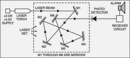
Here is a simple, low-cost intruder detector that uses an invisible laser beam to detect the intruder. The laser beam is produced using a 3V DC or 4.5V DC laser pointer or torch that is available in the market. The 3V DC or 4.5V DC power supply for the laser transmitter can also be given using a bridger ectifier or full-wave rectifier.

Fig. 1 shows the block diagram of the complete unit comprising the transmitter and receiver sections. The laser beam from the transmitter after reflection from various mirrors (M1 through M6, as shown in Fig. 1) is made to fall on the photodetector in the receiver schema.

 block diagram of intruder detector using laser torch

Fig. 1: Block diagram of intruder detector using laser torch

Once the laser beam is positioned, the receiver schema is powered by closing switch S. An alarm unit operating on 230V AC is connected to the relay RL in the receiver schema.

When an intruder interrupts the path of the beam or switches off the laser torch, the alarm unit becomes activated. The alarm unit remains activated until reset switch S is opened. To activate the alarm schema again, reset switch S should be closed. The total distance travelled by the laser beam should be less than 800 m for 4.5V laser torch and 500 m for 3V laser torch.

The schema of the receiver is shown in Fig. 2. When reset switch S is closed, the schema is powered on. As the laser beam falls on the photodetector, transistor T (BC547) conducts, resulting in the collector being pulled down to ground potential. Thus no current flows to the gate of the SCR and it remains off.


Receiver
Fig. 2: Receiver schema

Once the path of the laser beam is interrupted, the base current of the transistor becomes very low and the transistor is driven to cut-off. Now the current starts to flow through resistor R1 and to the gate of SCR. Hence the SCR is fired and it begins to conduct. Thus relay RL connected to the anode of SCR is switched on and the alarm is activated. The alarm sounds until reset switch S is opened to turn off power to the schema.

EFY Lab note. We tested the schema using only one mirror and found its range to be 25-30 metres. The range depends on the intensity of laser beam falling on the photodetector.

The schema (excluding laser torch and mirrors) costs around Rs 100.


Sourced By: EFY Author:  G. Susinder Rajan
ReadMore..

Sunday, August 31, 2014

How to Build Toxic Gas Detector and Alarm Circuit with TGS813

The danger always exists, when the fuel gases such as propane or gas are confined to a small area. The alarm of toxic gases figs. 1-45 utilizes a tin-oxide-semiconductor. A coil of thin wire heated by a battery 12 V via IC1 and IC2, which pulses the voltage to the coil of the sensor, saving a significant amount of energy. Diode Zener Dl provides a constant voltage to the filament coil sensor. resistance of the sensor reduces the sensor is exposed to toxic gases such as hydrogen, carbon

Carbon monoxide and propane. To reduce the resistance of the sensor, the SCR gate voltage increases. When the gate threshold voltage is reached, the SCR fires and a buzzer alarm is activated. Once activated, the bell and the switch S1 should be used to reset the alarm. Since the sensor has a good deal of thermal inertia, S1 must be off or open for about three or four minutes after the initial activation, allowing the sensor to stabilize, thus avoiding false alarms. R7 sensitivity control set to the desired value, before the activation of SCR.

How

The toxic gas alarm is sensitive to less than 100 ppm of carbon monoxide. This alarm is useful for simple gas boats, sheds and cabins. You could save a life. Some of the companies listed in the Appendix to offer plans and kits for various toxic gas sensors.

Part List
Part Description
C1 0,01-MFD, 25-V capacitor (disc)
1 9-V zener diode D1 (NTE139A)
1 D2 4-V diode zener (NTE5068A)
1 SCR D3 (NTE5408)
1 Q1 Transistor 2N2222
U1 1 CD4013 CMOS flip-flop
1 U2 CD4049 CMOS Inverter Hex
1 siren piezo BUZ 6-9V
1 S1-TGS203 toxic gas sensor (Figaro or equivalent)

ReadMore..

Wednesday, August 27, 2014

Heat Sensor Fire Detector Pyroelectric

Pyroelectric
Detect the presence of fire in the world of electronics can be done by detecting changes in temperature, the presence of UV ultraviolet rays and infrared light IR. Heat Sensor pyroelectric detectors Eltec E442-3 is a heat sensor (fire) that detect the presence of infrared ray IR, and therefore often called IR-EYE.

These sensors form of Lithium Tantalate pyroelectric parallel opposed dual element high gain detector with integrated analog signal processing. These sensors can detect heat changes from -40 to +70 degrees Celsius without change siginfikan of noise and sensitivity.

To use heat sensor pyroelectric detectors Eltec E442-3, it can take a kind of cone is covered with a fresnel lens to focus the direction of the infrared ray IR. Heat sensors then pyroelectric detectors Eltec E442-3 inserted into the cone is then connected to the microcontroller. Analog output value signals which when detects heat, the sensor will cause a drastic change in output voltage.
ReadMore..

Monday, August 18, 2014

Heat Detector Alarm using UM3561

A very simple heat detector alarm electronic project can be designed using the UM3561 sound generator schema and some other common electronic parts . This heat detector electronic schema project uses a complementary pair comprising npn and pnp transistor to detect heat Collector of T1 transistor is connected to the base of the T2 transistor , while the collector of T2 transistor is connected to RL1 relay T3 and T4 transistors connected in darlington configuration are used to amplify the audio signal from the UM3561 ic.

Circuit
When the temperature close to the T1 transistor is hot , the resistance to the emitter –collector goes low and it starts conducting . In same time T2 transistor conducts , because its base is connected to the collector of T1 transistor and the RL1 relay energized and switches on the siren which produce a fire engine alarm sound. This electronic schema project must be powered from a 6 volts DC power supply , but the UM3561 IC is powered using a 3 volt zener diode , because the alarm sound require a 3 volts dc power supply. The relay used in this project must be a 6 volt / 100 ohms relay and the speaker must have a 8 ohms load and 1 watt power.
 
 
Streampowers
ReadMore..