Showing posts with label memory. Show all posts
Showing posts with label memory. Show all posts
Wednesday, October 1, 2014
Make a Door Bell with Memory Circuit
On occasion it may be useful to know when a visitor has called in your absence. This is especially true in the case of an enforced absence when a visitor is expected. Confusion reigns supreme on these occasions.
The circuit here helps to rectify the ’ situation by providing a memory for the doorbell. On your return a LED will advise you whether or not a visitor called. The circuit is powered by the bell transformer via diode D1 and capacitor C1. This provides a d.c. voltage level sufficient for the memory’. Under normal conditions (with no one ringing the doorbell) transistor T1 will be switched off and T2 will be conduc- ting to provide a form of latch for T1. Obviously LED D3 will never light under these conditions! Now our visitor arrives! With a joyful cry of Avon calling’ they press the doorbell — only to lapse into total embarrasment when there is no answer! However our circuit now leaps into action. Via D2 and R 1, the doorbell switch S1 provides a base drive current to T1 which . switches off. T2 and, in passing, i LED D3 on. `&low thm transistor i ’latch’ (T2) swings the other way and T1 is held on by the current path to the positive supply through S2 (normally closed) R5 and R6. The unfortunate visitor goes away totally deflated but the LED will indicate his past presence’l On your return the LED will be noted and the circuit reset’.

This is carried out by simply pressing S2 which breaks the base currents path holding T1 on causing this transistor to switch off. In doing so the LED will be switched off and T2 will be switched on. The ’latch’ will be back in the original position where T1 is held off by the fact that R5 is effectively in parallel with R2. A further refinement would be to provide an automatic reset when the front door is opened. ln this case S2 is a switch operated by the opening door. However the LED must then be mounted outside the door (poss- ibly in the doorbell switch housing) or the LED will be off by the time you get into the house to look! On the other hand a second circuit could be built as a ’memory’ for the automatic’ memory and then it would be no problem to open the door! This second circuit will of course require a reset switch!
The circuit here helps to rectify the ’ situation by providing a memory for the doorbell. On your return a LED will advise you whether or not a visitor called. The circuit is powered by the bell transformer via diode D1 and capacitor C1. This provides a d.c. voltage level sufficient for the memory’. Under normal conditions (with no one ringing the doorbell) transistor T1 will be switched off and T2 will be conduc- ting to provide a form of latch for T1. Obviously LED D3 will never light under these conditions! Now our visitor arrives! With a joyful cry of Avon calling’ they press the doorbell — only to lapse into total embarrasment when there is no answer! However our circuit now leaps into action. Via D2 and R 1, the doorbell switch S1 provides a base drive current to T1 which . switches off. T2 and, in passing, i LED D3 on. `&low thm transistor i ’latch’ (T2) swings the other way and T1 is held on by the current path to the positive supply through S2 (normally closed) R5 and R6. The unfortunate visitor goes away totally deflated but the LED will indicate his past presence’l On your return the LED will be noted and the circuit reset’.
This is carried out by simply pressing S2 which breaks the base currents path holding T1 on causing this transistor to switch off. In doing so the LED will be switched off and T2 will be switched on. The ’latch’ will be back in the original position where T1 is held off by the fact that R5 is effectively in parallel with R2. A further refinement would be to provide an automatic reset when the front door is opened. ln this case S2 is a switch operated by the opening door. However the LED must then be mounted outside the door (poss- ibly in the doorbell switch housing) or the LED will be off by the time you get into the house to look! On the other hand a second circuit could be built as a ’memory’ for the automatic’ memory and then it would be no problem to open the door! This second circuit will of course require a reset switch!

Tuesday, September 16, 2014
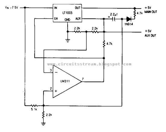
Memory Save on Power down Wiring diagram Schematic
Memory Save on Power down Circuit Diagram. The auxiliary output powers the memory, while the main output powers the system and is connected to the memory store pin. When power goes down, the main output goes low, commanding the memory to store. The auxiliary output then drops out.
Memory Save on Power down Circuit Diagram
Saturday, August 16, 2014
Read Only Memory
Memory group called Read Only Memory also has characteristics that match the name. Existing data in ROM, this is data that has been entered by the manufacturer. The data already contained in it can not be changed again through the normal process, and can only be read only. There are pieces of data in ROM is used for the identity of the computer itself. It is stored in the BIOS (Basic Input Output System). There are also data contained in this module was first accessed by a computer when it boots. Sequences contained in this module and are accessed the first time when the computer is turned on is called bootstrapping.
Subscribe to:
Posts (Atom)
