Friday, December 12, 2014
Lie detector schematic diagram

It's a simple lie detector that can be built in a few minutes, but can be incredibly useful when you want to know if someone is really telling you the truth. It is not as sophisticated as the ones the professionals use, but it works. It works by measuring skin resistance, which goes down when you lie.
Mosfet 1000W Power Inverter schematic

Stepper motor controller

Stepper Motor controller
The circuit is very simple and inexpensive. This is good thing because most commercial stepper motor controller ICs are quite expensive.
Labels:
controller,
motor,
stepper
Phone calling Detector

This circuit was designed to detect when a call is incoming in a cellular phone (even when the calling tone of the device is switched-off) by means of a flashing LED.The device must be placed a few centimeters from the cellular phone, so its sensor coil L1 can detect the field emitted by the phone receiver during an incoming call.
Amplifier Timer Schematic Diagram

This circuit turns-off an amplifier or any other device when a low level audio signal fed to its input is absent for 15 minutes at least.Pushing P1 the device is switched-on feeding any appliance connected to SK1. Input audio signal is boosted and squared by IC2A & IC2B and monitored by LED D4.
Radio Wave Alarm

This very simple alarm circuit is sure to have the police beating a path to your door - however, it has the added advantage of alerting you to their presence even before their footsteps fall on the doormat.
Thursday, December 11, 2014
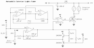
Automobile Light Fader

Here the circuit diagram of Interior Light Fader for Automobile.
The circuit is build using low power operational amplifier LM324 which only need around 3mA of current, so it won't bother the battery supply if left connected for extended periods.
Labels:
Automobile,
Fader,
light
Alarm Circuit
- A Transistor Based of Single Zone Alarm - If the building is not secure, when you switch the alarm on the buzzer will sound.
- Hijack Alarm - This circuit is designed primarily for the situation where a hijacker forces the driver from the vehicle. If a door is opened while the ignition is switched on, the circuit will trip.
- Car Alarm and Immobilizer - This circuit features exit and entry delays, an instant alarm zone, an intermittent siren output and automatic reset.
- Single Zone CMOS Alarm - This circuit has provision for normally open and normally closed switches and will accommodate the usual input devices such as Foil Tape, Pressure Mats, Magnetic Reed Contacts, Passive Infrared Detectors and Inertia (Shock) Sensors.
Subscribe to:
Posts (Atom)