Showing posts with label timer. Show all posts
Showing posts with label timer. Show all posts
Tuesday, January 6, 2015
Electronic Timer with display circuit

Using this electronic scheme can be built an electronic timer which can be set to measure a maximum of 60 hours.
The electronic timer allows the fixation of some intermediate time. On reaching this point, a buzzer will sound.
The circuit is built using ICM7217 integrated circuit, manufactured by Intersil, which contains a CMOS counter up / down, with 4 digits and display properly.

Friday, December 12, 2014
Amplifier Timer Schematic Diagram
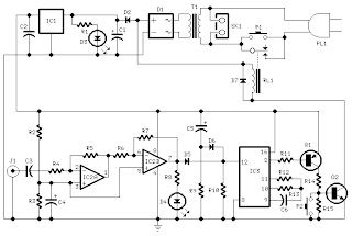
This circuit turns-off an amplifier or any other device when a low level audio signal fed to its input is absent for 15 minutes at least.Pushing P1 the device is switched-on feeding any appliance connected to SK1. Input audio signal is boosted and squared by IC2A & IC2B and monitored by LED D4.
Sunday, November 16, 2014
10 Minutes timer with 555
Applications of 555 timer IC is very diverse, one series of 10 Minute Timer with IC 555. 10 Minute Timer This circuit uses IC NE555 is set as a monostable multivibrator. The timing of the timer circuit 10 minutes with the IC 555 is governed by the configuration of C2, R4 and R5. The greater the value of C2 at 10-minute timer circuit with IC 555 timer is active then the time will stay longer. Total resistance value between R4 and R5 also determine the active circuit 10 minute timer with IC 555, where the greater the value the longer time was also active. The core active setting the timer on the set of C2 charging time for 10 minutes on the timer circuit with IC 555. So, with the value of C2 remain so with time on the circuit timing Timer 10 minutes by IC 555 can be set by changing the resistance value R 4 + R 5. Indicators of active timer at 10 minute timer circuit with IC 555 uses the LED D2 and D3 will light up only one course to identify the active timer and the timer has not been met.
Figure 10 Minute Timer circuit with IC 555 
Description:
S1 is used to set / reset timer
R5 is used to set the timer to the desired time
Friday, October 24, 2014
NE555 IC Timer
The 555 Timer is an integrated circuit (chip) implementing a variety of timer and multivibrator applications. The IC was designed and invented by Hans R. Camenzind. It was designed in 1970 and introduced in 1971 by Signetics (later acquired by Philips). The original name was the SE555/NE555 and was called "The IC Time Machine".
 The 555 gets its name from the three 5-k Ohm resistors used in typical early implementations. It is still in wide use, thanks to its ease of use, low price and good stability. As of 2003[update], 1 billion units are manufactured every year.
The 555 timer is one of the most popular and versatile integrated circuits ever produced. It includes 23 transistors, 2 diodes and 16 resistors on a silicon chip installed in an 8-pin mini dual-in-line package (DIP-8).
The 555 has three operating modes:
* Monostable mode: in this mode, the 555 functions as a "one-shot". Applications include timers, missing pulse detection, bouncefree switches, touch switches, Frequency Divider,Capacitance Measurement, Pulse Width Modulation (PWM) etc
* Astable - Free Running mode: the 555 can operate as an oscillator. Uses include LED and lamp flashers, pulse generation, logic clocks, tone generation, security alarms, pulse position modulation, etc.
* Bistable mode or Schmitt trigger: the 555 can operate as a flip-flop, if the DIS pin is not connected and no capacitor is used. Uses include bouncefree latched switches, etc.
The connection of the pins is as follows:

Nr. Name Purpose
1 GND Ground, low level (0V)
2 TR A short pulse high → low on the trigger starts the timer
3 Q During a timing interval, the output stays at +VCC
4 R A timing interval can be interrupted by applying a reset pulse to low (0V)
5 CV Control voltage allows access to the internal voltage divider (2/3 VCC)
6 THR The threshold at which the interval ends (it ends if U.thr → 2/3 VCC)
7 DIS Connected to a capacitor whose discharge time will influence the timing interval
8 V+, VCC The positive supply voltage which must be between 3 and 15 V
In the astable mode, the high time from each pulse is given by
high = 0.693.(R1 + R2).C
and the low time from each pulse is given by
low = 0.693.R2.C
where R1 and R2 are the values of the resistors in ohms and C is the value of the capacitor in farads.
Specifications
These specifications apply to the NE555. Other 555 timers can have better specifications depending on the grade (military, medical, etc).
* Supply voltage (VCC) 4.5 to 15 V
* Supply current (VCC = +5 V) 3 to 6 mA
* Supply current (VCC = +15 V) 10 to 15 mA
* Output current (maximum) 200 mA
* Power dissipation 600 mW
* Operating temperature 0 to 70 °C
Monday, August 18, 2014
0 to 20 seconds timer
Most of people asked about a short time timer.So I decided to introduce you this one.Here The time is adjustable from 0 to about 20 seconds.you can chang the time of it by changing the C1 Capacitor.So try this..
Parts:
R1 1 Meg Pot
R2 10 K 1/4 Watt Resistor
D1,D2 1N914 Diodes
C1 10uf 16V Electrolytic Capacitor
C2 0.01uf Ceramic Disc Capacitor
U1 555 Timer IC
RELAY 9V Relay
S1 Normally Open Push Button Switch
Note
# Use R1 to chang the time of Timer
# By changing the C1 capacitor You can change the time of timer
Tuesday, August 12, 2014
Simple fire alarm circuit using IC timer NE555
Here the simple file alarm schema based timer ID NE555. The works is simple, the lamp give light to the LDR (Light Depending Resistor) as light sensor. When the light from the lamp covered with smoke then the LDR will change its resistance value and then activated the alarm.

The thermistor offers a low resistance at high temperature and high resistance at low imperature. This phenomenon is employed here for sensing the fire.
The IC1 (NE555) is configured as a free running oscillator at audio frequency. The transistors T1 and T2 drive IC1. The output(pin 3) of IC1 is couples to base of transistor T3(SL100), which drives the speaker to generate alarm sound. The frequency of NE555 depends on the values of resistances R5 and R6 and capacitance C2.When thermistor becomes hot, it gives a low-resistance path for the positive voltage to the base of transistor T1 through diode D1 and resistance R2.
Capacitor C1 charges up to the positive supply voltage and increases the the time for which the alarm is ON. The larger the value of C1, the larger the positive bias applied to the base of transistor T1 (BC548). As the collector of T1 is coupled to the base of transistor T2, the transistor T2 provides a positive voltage to pin 4 (reset) of IC1 (NE555). Resistor R4 is selected s0 that NE555 keeps inactive in the absence of the positive voltage. Diode D1 stops discharging of capacitor C1 when the thermistor is in connection with the positive supply voltage cools out and provides a high resistance path. It also inhibits the forward biasing of transistor T1.
ReadMore..
The IC1 (NE555) is configured as a free running oscillator at audio frequency. The transistors T1 and T2 drive IC1. The output(pin 3) of IC1 is couples to base of transistor T3(SL100), which drives the speaker to generate alarm sound. The frequency of NE555 depends on the values of resistances R5 and R6 and capacitance C2.When thermistor becomes hot, it gives a low-resistance path for the positive voltage to the base of transistor T1 through diode D1 and resistance R2.
Capacitor C1 charges up to the positive supply voltage and increases the the time for which the alarm is ON. The larger the value of C1, the larger the positive bias applied to the base of transistor T1 (BC548). As the collector of T1 is coupled to the base of transistor T2, the transistor T2 provides a positive voltage to pin 4 (reset) of IC1 (NE555). Resistor R4 is selected s0 that NE555 keeps inactive in the absence of the positive voltage. Diode D1 stops discharging of capacitor C1 when the thermistor is in connection with the positive supply voltage cools out and provides a high resistance path. It also inhibits the forward biasing of transistor T1.
Subscribe to:
Posts (Atom)
