Showing posts with label by. Show all posts
Showing posts with label by. Show all posts
Thursday, November 13, 2014
Re using fused tube light by 4 diode
A tube-light get fused due to use from a long time. You may notice that a used fluorescent tube-light get black colored on the both end of it. This circuit is to light-up those fused tube-light.
Have you think about re using a fused tube light? (Which is usually thrown out). Well here I’m showing a simple circuit using 4 diode for re-using a fused tube light.
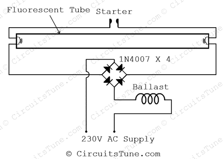
The circuit diagram shown above is quite simplified from basic tube light wiring diagram by adding a bridge rectifier. Bridge rectifier provides high voltage DC to the both end of tube. All we have focused in this project is to lighting-up the weak tube using high voltage DC.
Note: A fully damaged or broken tube-light could not be light-up anyway. Use those tube-light for this project that is still trying to light-up but not fully lightened on the basic connection of tube-light.
Have you think about re using a fused tube light? (Which is usually thrown out). Well here I’m showing a simple circuit using 4 diode for re-using a fused tube light.
The circuit diagram shown above is quite simplified from basic tube light wiring diagram by adding a bridge rectifier. Bridge rectifier provides high voltage DC to the both end of tube. All we have focused in this project is to lighting-up the weak tube using high voltage DC.
Note: A fully damaged or broken tube-light could not be light-up anyway. Use those tube-light for this project that is still trying to light-up but not fully lightened on the basic connection of tube-light.

Sunday, October 5, 2014
Peak Level Indicator by IC LM72 latest
Circuit Peak Level Indicator by LM723
This the circuit checks signal sound level or Circuit Peak Level Indicator by LM723. Usual we often lead IC LM723 or UA723 come to use do , DC voltage Regulator. But for this circuit , build the circuit can check signal sound level with. When see the structure changes the integrated circuit. As a result participate of check volage with then bring apply for this not difficult work extremely. As a result request friends study the work has of the circuit follows a picture be lucky sir.
Wednesday, September 10, 2014
Simple Thermal Fan Controller By IC 741
The controller uses one or more ordinary silicon diodes as a sensor, and uses a cheap opamp as the amplifier. I designed this schema to use 12V computer fans, as these are now very easy to get cheaply. These fans typically draw about 200mA when running, so a small power transistor will be fine as the switch. I used a BD140 (1A, 6.5W), but almost anything you have to hand will work just as well.
Thermal Fan Controller By IC 741 Circuit diagram:
Thermal Fan Controller Circuit Diagram
Source: ESP
Subscribe to:
Posts (Atom)
