Showing posts with label diode. Show all posts
Showing posts with label diode. Show all posts
Thursday, November 13, 2014
Re using fused tube light by 4 diode
A tube-light get fused due to use from a long time. You may notice that a used fluorescent tube-light get black colored on the both end of it. This circuit is to light-up those fused tube-light.
Have you think about re using a fused tube light? (Which is usually thrown out). Well here I’m showing a simple circuit using 4 diode for re-using a fused tube light.
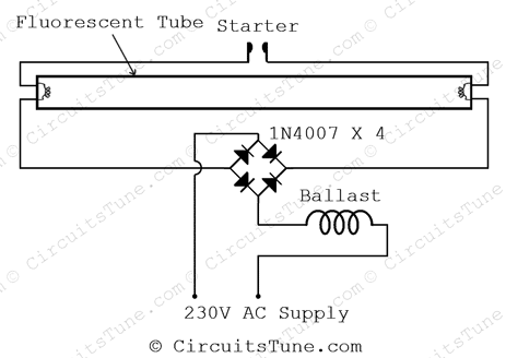
The circuit diagram shown above is quite simplified from basic tube light wiring diagram by adding a bridge rectifier. Bridge rectifier provides high voltage DC to the both end of tube. All we have focused in this project is to lighting-up the weak tube using high voltage DC.
Note: A fully damaged or broken tube-light could not be light-up anyway. Use those tube-light for this project that is still trying to light-up but not fully lightened on the basic connection of tube-light.
Have you think about re using a fused tube light? (Which is usually thrown out). Well here I’m showing a simple circuit using 4 diode for re-using a fused tube light.
The circuit diagram shown above is quite simplified from basic tube light wiring diagram by adding a bridge rectifier. Bridge rectifier provides high voltage DC to the both end of tube. All we have focused in this project is to lighting-up the weak tube using high voltage DC.
Note: A fully damaged or broken tube-light could not be light-up anyway. Use those tube-light for this project that is still trying to light-up but not fully lightened on the basic connection of tube-light.
Wednesday, October 15, 2014
Diode Cmos Stabilizer Circuit Diagram
The simple diode network can stabilize the voltage supplied to CMOS circuitry from a battery. D1 and D2 must have a combined forward-voltage drop of about 1.5 V. And D3 is an LED with a forward-voltage drop of about 1.7 V. The table shows the network`s output voltage as the battery`s voltage declines.
Diode Cmos Stabilizer Circuit Diagram

Monday, September 8, 2014
New Zener Diode Wiring diagram Schematic
Here we used the 12-0-12 step-down 500mA power transformer. The output of the transformer is supply to the bridge rectifier made of D2 , D3, D4, D5 which is use to convert the Ac supply to the DC supply. Capacitor C1 is used as a filter the DC output. We used 470 μF capacitor but you can used any. More the value of capacitor more pure DC can be obtained. Resistor R2 of 2.2K is used as bleeder. Here you can see the transistor T1 [BC147B] and transistor T2 [SL100] are use for regulator compressor.
The DC output is fed to these transistors. T1 acts as a series pass driver or a current regulator. Base bias for transistor T1 is achieved from the supply through resistor R3 of 680 ohms as resistor R2 of 10k is a base bleeder and capacitor C2 1 μF filters base potential. When the test probe is fully open with no zener connected, the base potential of transistor T1 is around 32V that is across resistor R4 or capacitor C2.
New Zener Diode Circuit Diagram

Transistor T1 [BC147B] provides the base potential for transistor T2 [SL100] which acts as a series pass regulator, providing the net DC voltage equivalent to T1 base potential which is fed to the voltmeter.
Now, the voltmeter reads around 30V with no zener diode connected across the probe. When a zener diode is connected across the test probe, the base potential of transistor T1 falls to zener diode breakdown voltage. With this, the base potentials for transistor T2 and transistor T1 become equal. The meter now shows the actual zener voltage. An adjustment of 0.6 V can be done on the meter scale by shifting the needle with zero adjustment screw on the meter.
Saturday, August 23, 2014
Affordable Vhf Uhf Diode Rf Switch Wiring diagram Schematic
This is the very cheap low priced schema. This is an affordable Vhf/Uhf diode Rf switch schema diagram. This schema uses low-cost IN4148 diodes and exhibits about 1.5 dB insertion loss from 10 to 1000 MHz with a few volts of negative bias. D3 conducts and D1/D2 are cut off, which results in 30 to 50 dB isolation. When a few volts of positive bias are applied, Dl and D2 are biased on and D3 is cut off. This schema should be useful in applications where a low-cost RF switch is necessary.
Affordable Vhf-Uhf Diode Rf Switch Circuit Diagram

Subscribe to:
Posts (Atom)