Thursday, November 13, 2014

Audio Test Equipment from Audio Millivoltmeter

When performing any tests on an audio system, some form of measuring device is essential. Digital multimeters are not useful, since they will not give the true picture of what is happening, and most have a fairly limited frequency range. An oscilloscope equipment is the ideal tool for audio test, but not all hobbyists can afford the outlay for a scope, and would find justifying the not inconsiderable cost a tad difficult.

An AC millivoltmeter - calibrated in dB - with a range of 30V down to 3mV full scale (80dB range) would be extremely useful. Attach a microphone (electret mic capsules are quite good), and you have a relative audio or sound level meter, even better if you have some way of calibration. The meter presented here has a very wide frequency range, and uses a switched attenuator for audio range adjustment. The attenuator uses the 30-10-3 sequence, which provides 10dB steps between ranges. The standard attenuator provides an input impedance of over 2M Ohms, but is a nuisance because with such high impedances stray capacitance causes havoc with the calibration, so a parallel capacitive attenuator is also needed. If you expect to work with valve amplifiers, you will want the high impedance, but otherwise the low impedance attenuator should do nicely.

The AttenuatorsThe two attenuator networks are shown in Figures 1 and 2, and as you can see the Hi-Z version requires all those capacitors. They must be accurate, too. Otherwise high frequency performance will be all over the place, so you need a capacitance meter or a source of close tolerance caps. The resistors are standard E24 series 1% metal film types, and the caps (if used) should ideally be polystyrene or polyester, but if ceramic is all you can get, then ceramics are what you use. If you do have to use ceramic caps, make sure that they have low thermal drift - NPO or similar.

AmplifierThe amplifier(s) used in such a audio test project are critical - we need wide bandwidth and low noise, coupled with low current drain, since we want to be able to run the meter on a 9V battery. The meter amplifier also requires high input impedance - especially for the high impedance attenuator version.

Complete Meter AmplifierThe entire audio test circuit can be built easily on a piece of perforated board (Veroboard or similar is good for this type of circuit), and a printed circuit board is quite unnecessary. Lay the physical circuit out following the schematic layout as closely as possible. This nearly always works well with discrete circuits, and makes it easy to follow 10 years later when you need to fix it. (I have had mine for nearly 20 years, and have not had to fix it yet.)

Test and CalibrationThe initial test involves connecting the meter amp to the attenuator, and applying power. All wiring must be carefully checked before you do this - the 9V batteries can supply enough current to damage the transistors, but batteries are more expensive than the transistors, and a wiring mistake may place a heavy discharge on the batteries rendering them dead before their time. Normally, batteries should last for quite a while, since the current drain is only about 4.5mA. 
ReadMore..

Re using fused tube light by 4 diode

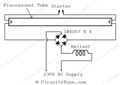
A tube-light get fused due to use from a long time. You may notice that a used fluorescent tube-light get black colored on the both end of it. This circuit is to light-up those fused tube-light.
Have you think about re using a fused tube light? (Which is usually thrown out). Well here I’m showing a simple circuit using 4 diode for re-using a fused tube light.

use


The circuit diagram shown above is quite simplified from basic tube light wiring diagram by adding a bridge rectifier. Bridge rectifier provides high voltage DC to the both end of tube. All we have focused in this project is to lighting-up the weak tube using high voltage DC.

Note: A fully damaged or broken tube-light could not be light-up anyway. Use those tube-light for this project that is still trying to light-up but not fully lightened on the basic connection of tube-light.
ReadMore..

Wednesday, November 12, 2014

Long Interval Pulse Generator

A rectangular-wave pulse generator with an extremely long period can be built using only two components: a National Semiconductor LM3710 supervisor IC and a 100-nF capacitor to eliminate noise spikes. This circuit utilises the watchdog and reset timers in the LM3710. The watchdog timer is reset when an edge appears on the WDI input (pin 4). If WDI is continuously held at ground level, there are not any edges and the watchdog times out. After an interval TB, it triggers a reset pulse with a duration TA and is reloaded with its initial value. The cycle then starts all over again. As a result, pulses with a period of TA + TB are present at the RESET output (pin 10).

Circuit diagram:
long-interval-pulse-generator-circuit-diagram Long-Interval Pulse Generator Circuit Diagram

long-interval-pulse-generator-diagram

As can be seen from the table, periods ranging up to around 30 seconds can be achieved in this manner. The two intervals TA and TB are determined by internal timers in the IC, which is available in various versions with four different ranges for each timer. To obtain the desired period, you must order the appropriate version of the LM3710. The type designation is decoded in the accompanying table. 

The reset threshold voltage is irrelevant for this particular application of the LM3710. The versions shown in bold face were available at the time of printing. Current information can be found on the manufacturer’s home page (www.national.com). The numbers in brackets indicate the minimum and maximum values of intervals TA and TB for which the LM3710 is tested. The circuit operates with a supply voltage in the range of 3–5 V.
ReadMore..

Booster II for Input Impedance

The input resistance of a.c.-coupled op amp circuits depends almost entirely on the resistance with which the d.c. setting is determined. If CMOS op amps are used, the input resistance is normally high, currently up to 10 MΩ. If a higher value is needed, a bootstrap circuit may be used. This enables the input resistance to be boosted artificially to a very high value, indeed In the circuit shown in the diagram, resistor R1 sets the d.c. point for IC1a. The terminal of the resistor linked to pin 7 of IC1 would normally be at earth potential, so that the input impedance would be 10 MΩ. Connecting the other terminal of the resistor to earth via IC1a and network C2-R3-R2 as far as d.c. is concerned results in the requisite d.c. setting of the op amp.Input
Input Impedance Booster II Circuit Diagram

As far as alternating voltages are concerned, the input signal is fed back so that only a tiny alternating current flows through R1. Therefore, Rin=R1[(R2+R3)/R3]. With resistor values as specified, Rin is about 1 GΩ. One aspect must be borne in mind: the numerical value of (R2+R3)/R3 must not exceed 0.99. This means that the value of R3 cannot be less than 100 kΩ if the value of R2 is 10 MΩ. If these conditions are not met, the circuit will become unstable
ReadMore..

Saturday, November 1, 2014

Ampere or Current Booster Circuit

Volt regulators such as the LM708, and LM317 series (and others) sometimes need to provide a little bit more current then they actually can handle. If that is the case, this little circuit can help out. A power transistor such as the 2N3772 or similar can be used.
The power transistor is used to boost the extra needed current above the maximum allowable current provided via the regulator.
Current up to 1500mA(1.5amp) will flow through the regulator, anything above that makes the regulator conduct and adding the extra needed current to the output load. It is no problem stacking power transistors for even more current. (see diagram). Both regulator and power transistor must be mounted on an adequate heatsink.


Circuit diagram:


Ampere or Current Booster Circuit Diagram


Parts:

R1 = 1R-2W
R2 = 10R-2W
C1 = 35v-470uF
C2 = 35v-470uF
Q1 = TIP2955
IC1 = 78xx Regulator
ReadMore..

Friday, October 31, 2014

Best Performance Interruption Detector Schematic

Best Performance Interruption Detector Schematic Circuit, The circuit presented here detects interruption in security systems. Its features include no false triggering by external factors (such as sun-light and rain), easy relative positioning of the sensors and alignment of the circuit, high sensitivity, and reliability. The circuit comprises three sections, namely, transmitter, receiver, and power supply. The transmitter generates modulated IR signals and the receiver detects the change in IR intensity. Power supply provides regulated +5V to the transmitter and the receiver. 

The power supply and the speaker are kept inside the premises while the transmitter and the receiver are placed oppo site to each other at the entrance where the detection is needed. Three connections (Vcc, GND, and SPKR) are needed from the power supply/speaker to the receiver section, while only two connections (Vcc and GND) are required to the transmitter. The transmitter is basically an astable multivibrator configured around NE555 (IC3). Its frequency should match the frequency of the detector/sensor module (36 kHz for the module shown in figure) in the receiver. The transmitter frequency is adjusted by preset VR2. For making the duty cycle less than 50 per cent, di-ode 1N4148 is connected in the charging path of capacitor C7. 

The output of astable multivibrator modulates the IR signal emitted from IR LEDs that are used in series to obtain a range of 7 metres (maximum). To increase the range any further, the transmitted power has to be raised by using more number of IR LEDs. In such a case, it is advisable to use another pair of IR LEDs and 33-ohm series resistor in parallel with the existing IR LEDs and resistor R5 across points X and Y. The receiver unit consists of a monostable multivibrator built around NE555 (IC2), a melody generator, and an IR sensor module. The output of the IR sensor module goes high in the standby mode or when there is continuous presence of modulated IR signal.

Circuit diagram :

 
High-Performance Interruption Detector Circuit Diagram
 
When the IR signal path is blocked, the output of the sensor module still re-mains high. However, when the block is removed, the output of the sensor module briefly goes low to trigger monostable IC3. This is due to the fact that the sensor module is meant for pulsed operation. Thus interruption of the IR path for a brief period gives rise to pulsed operation of the sensor module. Once monostable IC2 gets triggered, its output goes high and stays in that state for the duration of its pulse width that can be controlled by preset VR1. The high output at pin 3 of the monostable makes the musical IC to function. Voltage divider comprising R2 and R3 reduces the 555 output voltage to a safer value (around 3V) for UM66 operation. The du-ration of the musical notes is set by pre-set VR1 as stated earlier. 

For proper operation of the circuit, use 7.5V to 12V power supply. A battery backup can be provided so that the circuit works in the case of power failure also. Potmeter VR3 serves as a volume control. The transmitter, receiver, and power supply units should be assembled separately. The transmitter and the receiver should have proper coverings (booster) for protection against rain. The length of the wire used for connecting the IR sensor module and IR LEDs should be minimum. 

Note. 
 
The heart of the circuit is the IR sensor module (usually used in VCRs and TVs with remote); the circuit works satisfactorily with various makes of sensors. The entire circuit can be fixed in the same cabinet if the connection wires to the sensors are smaller than 1.5 meters. The reflection property of IR signals can also be used for small distance coverage. 


Sourced By: www.streampowers.blogspot.com
ReadMore..

VW Passat 1 L 2001 Headlights Wiring Diagram

VW
Headlights Wiring Diagram VW Passat 1.L 2001
Look inside behind the fuse panel. You’ll see the relay panel and relay 173. A closer look at relay 173 installed. Pull relay 173 out to disable the daytime running, Second method: Modifying the light switch The pin connectors at the back of the light switch lights. The object here is to stop electrical current from traveling through these pins.

For MY 1998-2001 Passats (B5) tape over, bend, or break pin TFL to disable the DRL when the light switch is in the OFF position. For MY 2001.5-2003 Passats (B5.5) tape over, bend, or break pin B to disable the DRL when the light switch is in the OFF position.

Here VW Passat 1 L 2001 Headlights Wiring Diagram

ReadMore..