Friday, December 12, 2014

Lie detector schematic diagram


It's a simple lie detector that can be built in a few minutes, but can be incredibly useful when you want to know if someone is really telling you the truth. It is not as sophisticated as the ones the professionals use, but it works. It works by measuring skin resistance, which goes down when you lie.
ReadMore..

Mosfet 1000W Power Inverter schematic

circuit-schematic-power
This power inverter circuit will provide a very stable “Square Wave” Output Voltage. Frequency of operation is determined by a pot and is normally set to 60 Hz. Various “off the shelf” transformers can be used. Or Custom wind your own for best results.
ReadMore..

Stepper motor controller

motor-driver-circuit

Stepper Motor controller

The circuit is very simple and inexpensive. This is good thing because most commercial stepper motor controller ICs are quite expensive.
ReadMore..

Phone calling Detector

phone-schematic-diagram


This circuit was designed to detect when a call is incoming in a cellular phone (even when the calling tone of the device is switched-off) by means of a flashing LED.The device must be placed a few centimeters from the cellular phone, so its sensor coil L1 can detect the field emitted by the phone receiver during an incoming call.
ReadMore..

Amplifier Timer Schematic Diagram

amplifier-timer-schematic

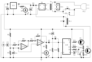
This circuit turns-off an amplifier or any other device when a low level audio signal fed to its input is absent for 15 minutes at least.Pushing P1 the device is switched-on feeding any appliance connected to SK1. Input audio signal is boosted and squared by IC2A & IC2B and monitored by LED D4.
ReadMore..

Radio Wave Alarm

alarm-schematic-circuit-diagram

This very simple alarm circuit is sure to have the police beating a path to your door - however, it has the added advantage of alerting you to their presence even before their footsteps fall on the doormat.
ReadMore..

Thursday, December 11, 2014

Automobile Light Fader


light-fader-circuit
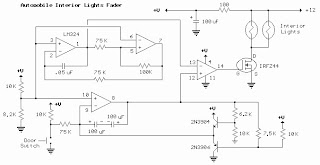
Here the circuit diagram of Interior Light Fader for Automobile. 

The circuit is build using low power operational amplifier LM324 which only need around 3mA of current, so it won't bother the battery supply if left connected for extended periods.
ReadMore..

Alarm Circuit

  1. A Transistor Based of Single Zone Alarm - If the building is not secure, when you switch the alarm on the buzzer will sound.
  2. Hijack Alarm - This circuit is designed primarily for the situation where a hijacker forces the driver from the vehicle. If a door is opened while the ignition is switched on, the circuit will trip.
  3. Car Alarm and Immobilizer - This circuit features exit and entry delays, an instant alarm zone, an intermittent siren output and automatic reset.
  4. Single Zone CMOS Alarm - This circuit has provision for normally open and normally closed switches and will accommodate the usual input devices such as Foil Tape, Pressure Mats, Magnetic Reed Contacts, Passive Infrared Detectors and Inertia (Shock) Sensors.
ReadMore..

Thursday, November 20, 2014

Ultrasonic Position System

The ultrasonic position system uses ultrasonic transmitters/receivers to triangulate position of the robots used in GE423. Each of three transmitters uses a distinct frequencies: 23 kHz, 31 kHz, and 40 kHz. The 2812 DSP is used to measure signal timing and calculate position based on these values. The design of the electronics, as well as discussion of the software development is presented below.

The electronics were not intergrated with the 6713 DSP on the robot.
Note: To get around the issue of clock syncing, the robot will start in a known position, and calculate position for four cycles before proceeding. An alternative to this would be to add a fourth transmit frequency and use the 4th signal to sync the robot clock with the transmit clock.

1.0 Hardware

A wide variety of hardware was used for this project. The hardware was chosen based on availability and price. By no means is the solution presented "the best"or the only way to achieve the desired results, but it is a workable solution.

1.1 Ultrasonic Transmitters/Receivers

The ultrasonic sensor were purchased from Massa. The TR-89/B series where chosen because they come in 3 different frequencies, and they were stock parts. There is no pdf data sheet available on the Massa website, all information if available here. The main drawback of using Massa is there $500 minimum order, and the sensors arent cheap at about ~$30 each.

1.2 Transmit Circuit

A schematic of the transmit circuit looks like:

Images of the perf-boarded transmit circuits:

Details on the components of the transmit circuit can be found in the subsection below:

1.2.1 Frequency Generation

The transmit circuit take from the Massa Website looks like:
Source:http://www.massa.com/datasheets/graphics/tr89_data.gif
Where R1 is a 10k 10 turn precision wound potentiometer, and U1 is a CD4039B NAND Schmitt Trigger. The tuning resistor R2 and L where left out to increase the transmit power around the base frequency. The potentiometer was adjusted until the frequency was the desired base frequency. A 1k resistor was added in parallel with the potentiometer to give a higher resolution. For the 40 kHz case, a smaller capacitor was required to reach the base frequency. Make sure to tune the circuit with the ultrasonic transducers attached, because the additional impedance will change the transmit frequency. The 12 Vdc was generated by a lab supply.
The output at point TP1, is a 12V peak to peak is a square wave at the desired frequency. The point TP1 was connected to the Driver Signal Circuit presented below.

1.2.2 555 Timer Circuit

The documentation for the 555 timer can be found here. An a picture of how it is wired can be 


seen below:
Source:http://www.williamson-labs.com/480_555.htm
Using the handy calculator for Ra, Rb, and C found here, Ra=100k ohm, Rb=200k ohm, and C=2.2 mircoF.

1.2.3 Driver Signal Circuit

The 35 Vdc supply is manufactured by Ultravolt, part number 1/4Aa24-P30. This supply is actually a 0-250 Vdc supply that uses a potentiometer to control voltage output.. The transistor used is an IRF520 n-channel MOSFET.

1.3 Receive Circuit

A block diagram of the receive circuit can be seen below:

And a picture of the perf-boarded receive circuit can be seen below:

Details on the components of the receive circuit can be found in the subsection below:


1.3.1 Low Signal Amp Circuit

An instrumentation amplifier made by Analog Devices was used to amplify the low signal output of the ultrasonic receivers. The actual part used was the AD620, one is recquired for each receive channel. Analog has a nice tool here, to size the gain resistor, Rg. Based on experiments, a gain value of 33 was chosen, resulting in a Rg of 1.5k ohm. The AD620 was wired as follows:
Source:http://www.analog.com/images/Product_Descriptions/3888333375812882340AD620_fbs.gif

1.3.2 Comparator Circuit

The analog comparitor used was part number LM339. The volatage divdier was powered using +5 Vdc to creat the digital level output signal. The output from each instrumentation amplifier was wired to the "+" terminal, and the "-" was wired to 3 volts. The 3 Vdc signal was created from the +15 Vdc supply using a voltage divider. The output of the comparitor was wired to a 5 Vdc via a 3k resistor.

2.0 Software

The timing of the hardware interrupts from the 2811 is calculated, and from the times, position is calculated in the 2D plane using a combination of least squared fit and Jacobian iteration.

2.1 Matlab Triangulation Code

The first algorithm was developed using Matlab. This code can be found here. The algorithm is not stable for all input parameters, a good set of test conditions are:
[x,y]=blah(.010,.012,.012)
[x,y]=blah(.009,.014,.012)
[x,y]=blah(.011,.011,.011)
Note the highly descriptive function named blah

2.2 DSP C Code

The c code for the 2812 DSP is in the attached zip file. The code works as following:
  1. Hardware interrupt pin get triggered
  2. Record absolute clock time when pin transition occurs
  3. Go back to step 1,and once all three pins have been triggered:
    1. (only do this step the first time through the code) Assume robot stationary, acquire base transmit period for each frequency by averaging first 4 values, this step syncs the clocks of the transmitters to the robot
    2. Calculate time from transmitter to robot for each frequency
    3. Triangulate position of robot using least squared fit to data points
    4. Wait for fixed amount of time, ignore hardware interrupts during this time because of the nature of the transmit signal
    5. Go back to Step 1

3.0 Lessons Learned

  1. A resistor was needed in parallel with the tuning potentiometer to give better resolution
  2. A resistor was required in parallel with the US transmitter for the circuit to function because the transmitter is like a capacitor.

4.0 Acknowledgments

Various people and online resources aided in this project:
  • GE423 Lab Instructor: Dan Block
  • GE423 TAs: Dave Johnson, Daniel Herring
  • My officemate: Steve Tschopp
  • Misc. Consultation: Tim Cargol
  • Misc Websites:
    • http://ourworld.compuserve.com/homepages/Bill_Bowden/555.htm
    • http://www.williamson-labs.com/480_555.htm
    • http://www.massa.com
    • http://www.digikey.com (source for datasheets)
ReadMore..

170W power amplifier LM4651 and LM4652

Part of this power amplifier driver using the LM4651 IC designed specifically for the purpose of the class AB amplifier driver with short circuit protection feature, containing under voltage, thermal shutdown protection and standby functions. Section 170 Watt power amplifier using LM4651 IC with a MOSFET power amplifier is equipped with temperature sensors that will be used by IC LM4651 as controlnya thermal signal. IC IC LM4651 and LM4652 are designed specifically to each other in pairs to create a class AB power amplifier with protection features are detailed. Detailed series of 170 Watt power amplifier can be seen in thethe following figure .

170W

Power amplifier circuit requires supply voltages +22 V DC symmetrical 0-22V. Power Amplifier with IC LM4651 and LM4652 are often used in portable HiFi systems such as powered speakers, power subwoofer and car audio power Booter. D1, D2, D3 and D4 in series 170 watt power amplifier with LM4651 and LM4652 is a 22V zener diode.
ReadMore..

Flip Flop Led Circuit

Flip Flop LED
Flip flop circuit is a series of free runing multivibrator given the burden of LEDs on each side of the transition changes its output signal. Flip flop circuit with LEDs is quite simple, that is prepared with 2 units and 2 units of 2N3904 transistor circuit tank circuit composed by the RC circuit. 
LED indicators signal a change that is placed on each side of the flip flop will be lit in turn by the fire and extinguished the same as the charge and discharge capacitor. Flip flop circuit is quite simple as shown in the picture below.

Flip Flop LED series

The working principle is the flip flop over when the series voltage source is given then the 10uF capacitor will be charged through R 470 and the LED will then be forwarded to triger the transistor base so that the transistor will turn ON and LEDs. this occurs alternately on each side, so that the LED light will illuminate in turn as well.
ReadMore..

Temperature and Humidity Sensors

Temperature and humidity sensors used are SHT75. This sensor is a chip that can measure temperature and humidity as well. The use of these sensors with consideration of its small size and reliability. The output of this sensor has the form of digital data in the chip because it has been there for a 14bit ADC. Temperature measurement range between -40-123,8 º C and humidity between 0-100% Rh. measurement accuracy reaches ± 0.3 per increase in 25 º C for temperature and ± 1.8% RH for humidity.
Here is a picture of temperature and humidity sensors SHT75:


The default measurement resolution of this sensor is 14 bits to 12 bits and temperature sensors for humidity sensors, can also use only 12 bit resolution and 8 bits.

ReadMore..

Wednesday, November 19, 2014

Line Follower Robot Sensor Concept

Line Follower Robot Sensor Concept - Sensor line detector is used in line follower robot is usually based on the principle of light reflectionto distinguish the line with the background color. In the dark color of the light absorption is greater than that of white light reflected to the sensor becomes smaller.
Position sensor to track the trajectory and the example circuit.

Line Follower Robot Sensor Concept
Light used for the introduction of the line is usually visible light and infra-red. Sensors for visible light are commonly used are LDR (Light Depending Resistance), while for the infrared light is atransistor and photo diode (photodiode). Sensors placed at the bottom of the frame to hang the robot, so that its position can be located just above the track to be read.

ReadMore..

Audio Surround Decoder Circuit

The circuit schematic drawings Surround Audio Decoder and its components and how to make it ,Audio surround decoder circuit. Surround sound quality is the process of adding the audio source by increasing the number of speakers. This is done by producing audio multitracking in a way that can be issued on a multichannel speaker.


Basically surround adopt an existing stereo system. The system uses a two-speaker stereo is right speaker and left speaker. With two speakers will be three-dimensional effect of the sound issued. With the surround, which generated three-dimensional effect was more extensive than in stereo. This is because the surround speakers that use more than two pieces. In addition to supporting the three-dimensional effects, stereo field theory is also noteworthy to organize the arrangement of sounds based on the type of sound produced.

Component List :

R1-2-7-8-12-13-18-19-20 : 47Kohm
R3-4-5-6-21-22-34-35    : 10Kohm
R9-10-11-14-15-16-17    : 15Kohm
R23-24-25-33-36         : 100ohm
R26-27-28-31-32         : 100Kohm
R29-30                  : 5.6Kohm
C1-8                    : 47uF/25V
C2-7-9-14-23            : 47nF
C3-6                    : 1uF/100V
C4-5-10                 : 33pF
C11-12-15               : 10uF/25V
C13                     : 82nF
C16                     : 18pF
C17                     : 100pF mini adjustable capacitor
C18                     : 2.2nF
C19                     : 4.7uF/25V
C20                     : 100nF
C21                     : 10nF
C22                     : 180pF
C24                     : 150nF
RV1-RV2                 : 2 X 10Kohm  Log. pot.
RV3-4                   : 10K Log pot.
D1                      : 1N4148
IC1-6                   : TL072
IC2-3                   : TL074
IC4                     : MN3101
IC5                     : MN3004


Surround effects can only be listened to speakers who have more than two channels. Surround is a technique commonly used in todays films that utilize multichannel speakers. Surround allows voice can move from side to side, is a moving side to side is to move from one speaker to another speaker. To create three-dimensional sound effects you can use a series of audio surround decoder.
ReadMore..

IC Decade Counter 4017 Details

IC Decade Counter 4017

IC Decade Counter 4017 - CMOS 4000 series is a family of standard integrated circuits which implement a variety of logic functions using technology Complementary Metal-Oxide-Semiconductor, and is still used today. They were introduced by RCA as CD4000 COS / MOS in 1968, as a component with low power usage and a more flexible alternative to the 7400 series TTL logic chips.

While IC IC 4017 is a 16-pin CMOS decade counter CMOS 4000 series ICs. It takes input clock pulse at clock pin input and will make one of the ten pin output to "turn on / off" in sequence at each clock pulse changes.

Example of a simple circuit of ic 4017 is to create a series of "running LED" or LED running:

Example of a simple circuit of ic 4017


ReadMore..

Mini and simple power amplifier


What is the meaning of the picture above? The above picture is a miniature audio amplifier and very simple. Here I will give an audio amplifier schematic is very simple which only requires a few components only, can be seen under this scheme.


See from above scheme may occur to you, certainly cheap enough to make this amplifier and quite easy to make. The above simple audio amplifier circuit using an IC as the main amplifier and accompanied by other components. IC used is S1513, which requires a supply voltage ranging from 1.5 volts to 6 volts. And only 0.1 W output power with 4 ohm impedance. For a list components can be seen below.

Part list
C1 = 100nF
C2 = 100uF
C3 = 3n3F
C4 = 1uF
C5 = 1uF
U1 = S1513

ReadMore..

Skema Rangkaian Pengapian Motor CDI

The CDI ignition circuit produces a spark from an ignition coil by discharging a capacitor across the primary of the coil. A 2uF capacitor is charged to about 340 volts and the discharge is controlled by an SCR.


A Schmitt trigger oscillator (74C14) and MOSFET (IRF510) are used to drive the low voltage side of a small (120/12 volt) power transformer and a voltage doubler arrangement is used on the high voltage side to increase the capacitor voltage to about 340 volts.

A similar Schmitt trigger oscillator is used to trigger the SCR about 4 times per second. The power supply is gated off during the discharge time so that the SCR will stop conducting and return to its blocking state. The diode connected from the 3904 to pin 9 of the 74C14 causes the power supply oscillator to stop during discharge time. The circuit draws only about 200 milliamps from a 12 volt source and delivers almost twice the normal energy of a conventional ignition circuit.

High voltage from the coil is about 10KV using a 3/8 inch spark gap at normal air temperature and pressure. Spark rate can be increased to possibly 10 Hertz without losing much spark intensity, but is limited by the low frequency power transformer and duty cycle of the oscillator. For faster spark rates, a higher frequency and lower impedance supply would be required. Note that the ignition coil is not grounded and presents a shock hazard on all of its terminals. Use CAUTION when operating the circuit.

An alternate method of connecting the coil is to ground the (-) terminal and relocate the capacitor between the cathode of the rectifier diode and the positive coil terminal. The SCR is then placed between ground and the +340 volt side of the capacitor. This reduces the shock hazard and is the usual configuration in automotive applications.
ReadMore..

Audio phase shift oscillator Circuit Diagram

Here is a phase-shift audio oscillator with excellent distortion characteristics thanks to “softened” diode limiting provided by the 1N914 and resistor divider and degenerated gain provided by the 68 ohm emitter resistor. For minimum distortion, increase the 68 ohm resistor to a point just below where oscillation stops. A simple buffer may be added for driving lower impedance loads.


The output amplitude will be about 5 volts p-p but one of the 1N914’s 10k divider resistors may be changed for a different output amplitude. The circuit will work well with a power supply voltage other than 9 volts but the 68 ohm resistor may need adjustment
ReadMore..

Tuesday, November 18, 2014

Color Sensor with TSC230

Color Sensor TCS230 color sensor is a chip that works with the converting acceptance of a certain color of light emitted into the shape of frequency. TCS230 Color Sensor composed dri two main parts, namely a light-receiving section arranged in an array photodioda and Chaya koncerter this part to the frequency. Basically the TCS230 Color Sensor is a light sensor which is equipped with light filters for RGB primary color (Red-Green-Blue) and light sensor without the filter with scale 8 bits for each of this part of the sensor.
TSC230 Color Sensor

Pin Diagram

Photodiode the TCS230 Color Sensor arrays arranged in 8 × 8 with the internal configuration of the photodiode. 16 photodiode for the light sensor with a red light filter. 16 photodiode for the light sensor with a green light filter. 16 photodiode for the light sensor with a blue light filter. And 16 photodiode for light sensor without a color filter. On the use of Color Sensor TCS230 we can choose the color sensor with a filter of what we want to set the configuration data S2 and S3.
Photodiode the TCS230 Color Sensor will issue a magnitude comparable with current levels of primary color of light that happened to him. This current is then converted into pulses with a frequency proportional to the amount of current. TCS230 Color Sensor Output frequency can be made by adjusting the scale of the configuration data S0 and S1 of the selector pins S0 and S1 Color Sensor TCS230.
ReadMore..

Amplifier uses IC TDA7375A

4 channel amplifier uses an IC TDA7375A and capable of producing power 18watt output for each channel. TDA7375A amplifier circuit can be used to make 2 channel stereo configuration is often applied to sound systems in cars. That is 1 channel stereo for the front and 1 channel stereo for the the rear. Source voltage needed for this amplifier is a 12VDC-15VDC. Amplifier circuit with IC TDA 7375A is very simple and easy to make.


For more details can seen in the image circuit four channel amplifier TDA7375A follows.
Fund manager for the series 4 channel amplifier TDA7375A it can make use of the equalizer or tone controls. To manufacture ICs need to be considered cooling for IC TDA7375A because it will remove the heat.
ReadMore..

MC3479 Stepper Motor Driver

The circuit diagram is given here is a motor controller driver using the Motorola MC3479. The MC3479 is designed specifically for driving a stepper motor phase 2 in bipolar mode and is available in standard DIP and surface mount IC packages.The is compatible with TTL and CMOS and has selectable HI / LOW output impedance .

The output can deliver up to 350 mA each of the two coils of a stepper motor 2 phases. The change of output state occurs in the low to high transition of the input clock pulse. The new output will depend on the exit of age and state of the digital inputs. The output L1 to L4 are the results of high currents, which when connected to a stepper motor a two-phase full-bridge two formations.

Resistors R1 and Rb, Zener diode D1 and IC2 MC14049UB are additional components that are used in the circuit. R1 is an uprising and resistance Rb is used to set the maximum output sink. Zener diode D1 provides back emf protection.
ReadMore..

Triac Light Switch as a dimers

The series of light switches this time slightly different from the voltage of work. The series of light switches can work directly on the AC power network. Light switches are using the main component of TRIAC and LDR. The circuit is very simple and the components were sold in the market.

If you want a light reception sensitivity of this circuit can be arranged then the 3.3 MOhm resistor can be replaced with a variable resistor. For more details can be seen from the following series of images.
Triac Light Switch as a dimers Circuit Diagram

With Triac Light Switch series is as dimers, but dimers control performed by the reception of light around the LDR. The lower the intensity cayaha received LDR then  bright lights. For installation LDR need to be considered so as not exposed to light from the lamp directly.
ReadMore..

DC Motor Controller Circuit with NE555


A simple DC motor controller circuit with NE555 is shown here. several DC motor speed control circuits are revealed here however this can be the first one using NE555 timer IC. additionally to controlling the motors speed its direction of rotation will be also modified using this circuit.

A PWM circuit primarily based on timer NE555 is that the heart of this circuit. NE555 is wired as an astable multivibrator whose duty cycle will be adjusted by varying the POT R1. The output of IC1 is coupled to the base of transistor Q1 that drives the motor according to the PWM signal available at its base. Higher the duty cycle the typical voltage across motor will be high which ends in higher motor speed and vice versa. modification of DC motor direction is attained using the DPDT switch S1 that on application simply toggles the polarity applied to the motor.
ReadMore..

The parts of the Speaker

Basket (frame)
Made of a metal plate that will support all parts of the speaker where the speaker of the other speakers can be attached to the intact 

Magnet
Here is used to generate a magnetic field of permanent magnets to be used to drive the voice coil, so as to produce sound.

speaker
Parts of speaker
Voice Coil
Voice Coil is an important part of a speaker. Voice coil consists of Robbin (where rolled coil) and coil (the coil BWR - Brass Wire Rope), Coil is going to move in accordance with the signal diterirna.

Spieder or Damper
Spider or suspension dampers are used to speakers that serve to dampen the vibrations of the voice coil, so the voice coil can move freely.

Cone Paper
Paper Cone is part of the suspension of the speaker who serves simultaneously as an amplifier of vibration caused by the voice coil so it can form a clear voice signal received from the speakers.

Dust Cap
Dust Cap serves to channel sound vibration with paper cone and protect the inside of the speaker (where the air gap voice coil moves) from the dust and dirt.
see also : Subwoofer Amplifier
ReadMore..

Monday, November 17, 2014

What is LDR or Light Dependent Resistor

Light Dependent Resistor or LDR is a resistor that changes its resistance due to the intensity of light absorbed. LDR is also a resistor having a negative temperature coefficient, where the resistance is affected by light intensity.
 LDR or Light Dependent Resistor formed from cadium Sulfied (CDS) generated from ceramic powders.

In general, CDS also called conductive photo equipment, as long as the conductivity or resistance of CDS varies with light intensity. If the received light intensity is high then the barriers will also result in a high-voltage out also to be high and vice versa if the voltage is low. This is where the mechanism of the process of changing light into electricity occurs.
What is LDR or Light Dependent Resistor

CDS does not have the same sensitivity at each wavelength from ultraviolet up to infrared. This is called the characteristic spectrum and the response given by the manufacturer. CDS are widely used in planning a series of alternating (AC) compared with photo transistors and photo diodes.
ReadMore..

Know the Line Follower Robot

Line Follower Robot Glance - Line Follower Robot- a kind of robot which included into the category robotmobile are designed to work in an autonomous and have the ability to detect and move to follow (follows) the existing line on the surface. Control system used is designed to feel that there are pathways of movement and maneuver in order to remain able to follow that line. Robots of this type quite a lot of interest for those who are just learning to robot technology. Even competitions Line Follower Robot, often held regularly at various universities .In industry, robots of this type is often used to to move goods from one place to another. By modifying slightly the sensor line follower robot can then be developed into a Wall Follower Robot, a robot that can move around the wall.


Sensor On Line Follower Robot

Sensors, can be analogous to the eye of a robot that serves to read the black line of the track robot. So that the robot is able to know when he will turn right, when he turned left and when he stopped. The sensor used is a light sensor mounted below the front of the robot, so as to find a bright line of a dark background or vice versa. Sensors used are usually photo reflector, R LD (Light Dependent Resistor), Photo Diodes and Photo Transistor - mounted on the front two or more under robotline follower. There also are using the camera as a sensor (or image sensor) to a higher-resolution readout line, making more accurate robot motion.

The working principle of the sensor is simple, when the transmitter (infrared) emitting light onto a white field, the light will be reflected almost entirely by the white areas. In contrast, Itter m ans when emit light to dark or black areas, then the light will be absorbed by the dark areas, so that incoming light kereceiver low. To be able to read by the microcontroller, the sensor voltage should be adjusted to TTL voltage level that is 0-1 volts for logic 0 and 3-5 volts for logic 1. This can be done by installing the operational amplifier is used as a comparator.
ReadMore..

Digital basic logic gates

Digital basic logic gates, or often also called Boelan logic gates is a digital logic gate will output a logic 0 and 1 corresponds to the input received from each gate depends on the function logic. In the digital basic logic, there are 3 basic logic gates, ie AND gates, OR gates, NOT gates. Third this gate produces 4 next digital logic gates, namely: NAND gates, NOR gates, XOR gates, gate XAND.
Digital
AND Logic Gate
AND logic gate has the output formula AB = C, ie when both its inputs are not all the logic 1 output will be logic 0 and when both input logic 1 then the new output is logic 1.

OR Logic Gate
OR logic gate having an output summing function can be formulated A + B = C ie if one input is logic 1 then the output will be logic 1 and when both input logic 0 then the new output will be logic 0.

NOT logic gate
NOT logic gate or often also called inverting logic gates. NOT gate will output a value opposite of the input.
ReadMore..

DVD Player Circuits

However, if this is your aboriginal activity with an HC908 MCU, it is simpler to alpha from a allotment with the user adviser already programmed and known-good hardware, as the bargain M68DEMO908QT4 amateur kit.
gambar

A QT dent programmed with a tiny user-monitor allows the user to amount appliance programs, abode breakpoints and watch variables with about no aerial for the affairs running. ICD approach requires aloof one pin (PTA0) for abstracts transfer, a pushbutton to accumulate PTA2 ashore during reset, and a atomic interface for the PC consecutive port: see [3] [4] for a ambit schematic (compatible with the DVD-thermometer) and abundant programming explanations.

A actual advantageous affection of the QT MCU is accouterments abutment for one-pin ICD (in-circuit debug), authoritative an adversary accidental for best developers.

The ambit will not add aloof addition cable to the AV tangle: it is array powered. Four AA beef accumulation a absolute of 6 volts. Notably, a voltage regulator is unnecessary, but if you feel afflictive powering chips abutting to their best tolerable voltage you can consistently add one. I begin an electrolytic capacitor an two clarify capacitors are abundant to accommodate apple-pie power.

Timing attention is important to get actual alien ascendancy waveforms: the 1% blueprint for the centralized oscillator is not far from the accurateness of bowl resonators, which are frequently active in best alien controls.

With aloof eight genitalia and a battery, the accouterments can hardly be simpler. Ambit access is a aftereffect advancing beeline from the akin of affiliation of its capital components.

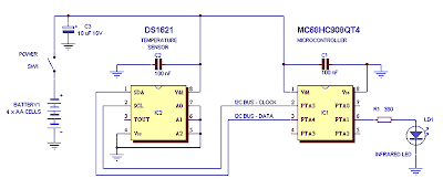
The temperature sensor IC is either a DS1621 or DS1631 (Maxim). This 8-pinner includes a complete agenda temperature sensor/thermostat with I2C output. With the adapted commands, the temperature can be apprehend from the consecutive interface with a affirmed accurateness of 0.5 °C, and a resolution of up to 0.1°C. It does not crave calibration, which is advantageous because you can assurance your thermometer after messing with ice and baking water.

Its pin 3 can assignment as a thermostat, but this affection is bare in this application. Pins 5…7 actuate the low $.25 of the accessory I2C abode (up to 8 sensors can be affiliated in alongside on the aforementioned I2C bus); ambience the access as apparent configures the accessory to acknowledge at abode 0×90.

The MCU is the Motorola MC68HC908QT4, a tiny 8-pin accessory with 4 kB of beam and 128 bytes of RAM. A nice appropriate of the QT is that all of its pins (except power) can be acclimated as I/O, as able displace is affirmed by agency of centralized brown-out circuitry, and a flash-calibrated centralized oscillator provides a analytic abiding alarm source.

Two I/O pins serve as I2C bus abstracts and clock. All QT pins affection programmable pull-ups, so alien resistors on the I2C bus are unnecessary.

Another I/O anchorage drives the IR LED (ports can antecedent up to 25 mA) through a accepted attached resistor. Peak accepted is set to 8 mA, abundant lower than a “real” alien control, because the accessory is advised to accomplish in abutting adjacency of the DVD player.

Rather, boundless LED ability may baffle with added IR accessories in the aforementioned location, e.g. air conditioners, TVs, VCRs, DVD players and others electronics appurtenances frequently begin in homes, offices and shops.
ReadMore..

FM Transmitter circuit using 2N2222


The FM transmitter circuit is using NPN transistor 2N2222. The L1 and C1 producess necessary oscillations Q1.The collector capacity C4, R3 and R4 resistor performs the function of the output mix theaudio to stereo player or i-emitter resistor R2 Pod.The provides sufficient stability for circuit.It also limits the collector current increse the battery.

With this circuit compact FM adapter connected to the audio output of your cassette player or i pod words, you can listen to your favorite music on the car track is stereo.This doesnot handy if your car stereo has an auxiliary circuit outlet is not to buy a short-range FM transimitter.
ReadMore..

Circuit Mobile Phone Battery Charger

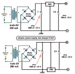
This post share about Mobile Phone charger circuits, previously you can see other Phone Battery Charger Circuit  or Charger Circuit . This Charger ciruit use to charging phone battery using IC 7805 for plus voltage regulator or & 7905 for min voltage regulator. Below is a schematic circuit adapter, power supply, or battery charger (for gadgets, mobile phones, MP4player, smartphone) that is equipped with a 5V voltage stabilizer:

adapter

Diode Bridge
diode bridge, known as a diode bridge is used for the rectifier circuit current (rectifier) from AC to DC. to make the diode bridge properly you need to know the type of diode to be used, to suit your needs. example: to make the power supply 12 Volt 3 ​​Ampere diode type 1N5401 is needed, for more detail how to choose the right type of diode to the adapter.

Voltage stabilizers are commonly used are the 78XX or 79XX type LM, XX indicates the maximum voltage output is generated. see the example in the circuit schematic above, to output 5 V is used type LM 7805. for other voltages must be adjusted to the transformer and its stabilizer IC.

ReadMore..

Sunday, November 16, 2014

10 Minutes timer with 555

Applications of 555 timer IC is very diverse, one series of 10 Minute Timer with IC 555. 10 Minute Timer This circuit uses IC NE555 is set as a monostable multivibrator. The timing of the timer circuit 10 minutes with the IC 555 is governed by the configuration of C2, R4 and R5. The greater the value of C2 at 10-minute timer circuit with IC 555 timer is active then the time will stay longer. Total resistance value between R4 and R5 also determine the active circuit 10 minute timer with IC 555, where the greater the value the longer time was also active. The core active setting the timer on the set of C2 charging time for 10 minutes on the timer circuit with IC 555. So, with the value of C2 remain so with time on the circuit timing Timer 10 minutes by IC 555 can be set by changing the resistance value R 4 + R 5. Indicators of active timer at 10 minute timer circuit with IC 555 uses the LED D2 and D3 will light up only one course to identify the active timer and the timer has not been met.
Figure 10 Minute Timer circuit with IC 555


Description:

S1 is used to set / reset timer
R5 is used to set the timer to the desired time
ReadMore..

Preamplifier Switching Center Module

PreamplifierPreamplifier Switching Center Module
Parts
R1,R2,R3,R4____100K 1/4W Resistors
R5_____________560R 1/4W Resistor

SW1,SW2________2 poles 4 ways Rotary Switches

J1 to J6_______RCA audio input sockets

This Module can be a all-important accession to the Modular Preamplifier Control Center back added than two sources charge to be affiliated to the preamplifier chain.

Four aerial akin inputs can be alleged by agency of SW1 and baffled to the output. The achievement of this bore charge be affiliated by a acceptable cable to one of the two inputs of the Control Center module. In this way, a absolute of bristles inputs will be accessible to the user of this bore combination.

The Switching Control appearance additionally the so alleged "Double Bar", i.e. the achievability of acquisition to an alien unit, e.g. a recorder (tape or digital) an ascribe arresting altered from that reproduced at the time by the amplifier.

For example, you can accept in to a CD admitting the arresting advancing from a radio base through the Tuner is baffled to the recorder. This alternative is operated by agency of SW2.

As with the added modules of this series, anniversary cyberbanking lath can be adapted into a accepted enclosure: Hammond extruded aluminum cases are able-bodied ill-fitted to host the boards of this preamp. In particular, the cases sized 16 x 10.3 x 5.3 cm or 22 x 10.3 x 5.3 cm accept a actual acceptable attending back stacked. See beneath an archetype of the accessible adjustment of the advanced and rear panels of this module.

Notes:

  • No power supply is necessary for this module
  • The circuit diagram shows the Left channel only, so all the parts must be doubled except SW1 and SW2 which are double pole switches, i.e. ready for stereo.
ReadMore..

Saturday, November 15, 2014

How to Build a Common-Emitter Proximity Detector

A proximity detector is gagdet that detects when an object is nearby. There are 2 ways to build a protximity detector. One is mount the IR LED and the phototransistor so that they face each other. Then the infrared light is detected by the phototransistor. If an object comes between the IR LED and the phototransistor, the light is blocked, and the phototransistor turns off.

The other way is to build a proximity detector is to mount the IR LED and the IR photodiode next to each other facing the same direction. When an object comes near the IR LED, some infrared light will bounce off the object and be detected by the phototransistor.

How to Build a Common-Emitter Proximity Detector

Parts
Phototransistor
33KΩ Resistor
330Ω Resistor
IR LED
9-volt Battery or DC Power Supply
Red LED

Schematic Diagram
Proximity Detector Circuit

ReadMore..

Friday, November 14, 2014

MOBILE PHONE JAMMER CIRCUIT

Circuit showing a mobile phone jammer. A FM transistor is used for making this circuit. Mobile phones are working in 450 MHz frequency. Here the transmitter generate almost equal to 450 MHz frequency, therefore the mobile phone does not identify the original signal. But the signal range is very week, so this circuit working in only 100 m range. This circuit working in only 450 Mhz . Do not give more than 3 V.

For any jammer circuit, remember that there are three main important circuits. When they are combined together, the output of that circuit will work as a jammer. The three circuits are
  • RF amplifier.
  • Voltage controlled oscillator.
  • Tuning circuit.

Circuit Diagram


Parts List 

ComponentsValue  Usage
R1         100R   Emitter loading
R2         39k    Base Biasing
C1         15 pf Frequency Generating
C2         4.7pf Feedback
C3         4.7pf Feedback
C4         102pf Noise Reduce
C5         1uF    Coupling
C6         2.2pf Coupling
C7         103pf  Decoupling 
Q1         BF 494 Amplification
L1         22nH   Frequency Generating
ReadMore..

AM RECIEVER CIRCUIT

It can use general purpose transistors, and in this example there are 3 BC109C transistors. The schematic and BOM show a 200µH inductor and a trimmer capacitor 150-500pF, though these parts can be salvaged from an old AM radio, to preserve the directional nature of a tuning coil, and an adjustment knob (plate capacitor) that work well for radio reception.
 
The 120k resistor is for regenerative feedback between the Q2 NPN transistor and the input to the tank circuit. The value of this resistor is important to the performance of the entire AM receiver. In fact, it may be better to replace the fixed value with a variable resistor paired with a fixed resistor to adjust the oscillation and sensitivity. All the connections should be short to minimize interference.

Performance will vary depending on stray capacitance in your layout, the inductor winding/core/length, etc. Changing values of some of the capacitors, or adding them, as well as a potentiometer in the feedback loop can help with the performance of the receiver. With such a small circuit that is affected so much by its construction and its environment, a lot of hand tuning and experimentation will be fun, instructive, and possibly necessary to make it work best.

Circuit Diagram


Parts List

Symbol                     Name                                        Value
C1              VARIABLE                500pF
C2              NON POLARIZED           0.1uF
L1              AIR CORE                200uH
Q1              NPN
Q2              NPN
Q3              NPN
R2              RESISTOR                1K
R3              RESISTOR                330K
C3              NON POLARIZED           0.1uF
R1              RESISTOR
R4              RESISTOR                560K
R5              RESISTOR                10K
C4              NON POLARIZED           0.1uF

Application

A small, simple AM receiver project with only 3 transistors. This circuit can pick up medium wave stations in your area.

ReadMore..

IC 74hc14 Arrow led indicator circuit with explanation


This arrow led indicator electronic project can be used in some dark places to show the directions . You can use to indicate direction just an illuminated arrow or a flashing light , but is much nicer if the light moves in the correct direction.
This arrow led indicator is based on 74HC14 circuit and some LEDs which are used to show the way .

For this arrow led indicator we need six series of three LEDs arranged in the shape of arrows and are connected to the outputs . Each time the lit arrows move over by one column so it appears that the arrows run from right to left.
If we want to change the speed of the moving light it’s need to change the value of C1 to C3 or R1 to R3 ( a lower value for this components decrease the time of moving lights) .
If we want a longer arrow we can mount in parallel with existing columns another columns .
For power supply we can use batteries or 6V regulated power supply .

ReadMore..

Thursday, November 13, 2014

Water Sensor Circuit Diagram using IC 555

This is a water sensor /rain alarm circuit diagram; it can be used on motorcycle, car or other device that we want to protect from water, rain.
This is a simple water sensor/rain alarm circuit that makes an alarm when water/rain falls on its sensor. This circuit is based on NE555/LM555 IC and two transistors (Q1&Q2). For  transistor Q1- BC547 or BC107 and for Q2-  2N825,BC548 or BC168 can be used in the circuit. This rain detector circuit can be supplied from voltage source of +9V-12V DC. The resistor 470K ohm is a POT/Variable resistor; it is used to adjust the sensitivity of water/rain sensor. Use a 8 ohm,0.5w-1W  speaker to hearing  better alarm. Less than 8 ohm speaker could be harmful for the IC 555.

Circuit Diagram of Water Sensor

Fig-1: Water Sensor/Rain alarm circuit diagram

Water sensor PCB layout:

Fig-2: PCB layout of water sensor
We can make the water sensor as shown in the image (Fig-2) using aluminum conductor like a naked wire . Here can be used other conductor but we suggesting to use aluminum.
ReadMore..

88 108 MHz PLL FM Synthesizer

This fm synthesizer circuit is played with and optimised design for an 88-108 MHz synthesiser, programmable in 25 kHz steps. It produces about 50 mW output (and thus feeds nicely into the amplifier shown below) with no tuning required other than to set the inputs of the divide-by-N counter to the wanted frequency.

FM modulation is achieved just by injecting audio on the audio input (audio response is pretty flat from 10 Hz to over 200 kHz so can be used for stereo and RDS). This versatile design has also been used for link transmitters at around 48, 52 and 200 MHz with a few changes in the VCO and output filter, and by changing the reference crystal you can alter the channel spacing too. The power output is switched off until the synthesiser achieves lock to prevent transmissions on the wrong frequency (which can be disasterous if youve amplified it to high power and got it connected to a highly resonant antenna).
ReadMore..

LM317 Circuit

Introduction
The LM317 is AN adjustable three terminal transformer that is capable of supply 1.2 to 37 volts with a secure 1.5A output current. The LM317 is prepackaged terribly} normal electronic transistor package that makes it very simple to mount in your circuits. 
Schematic


Overview
The LM317 series of adjustable 3-terminal positive voltage regulators is capable of supply in more than 1.5A over a 1.2V to 37V output vary. theyre exceptionally simple to use and need solely 2 external resistors to line the output voltage. Further, each line and cargo regulation square measure higher than normal mounted regulators.

In addition to higher performance than mounted regulators, the LM317 series offers full overload protection out there solely in ICs. enclosed on the chip square measure current limit, thermal overload protection and safe space protection.

The LM317 makes AN particularly easy adjustable change regulator, a programmable output regulator, or by connecting a set electrical device between the adjustment pin and output, the LM317 may be used as a preciseness current regulator. provides with electronic conclusion may be achieved by clamping the adjustment terminal to ground that programs the output to one.2V wherever most masses draw very little current.

Pinout

Options


Specifications

  • Guaranteed 1% output voltage tolerance (LM317A)
  • Guaranteed max. 0.01%/V line regulation (LM317A)
  • Guaranteed max. 0.3% load regulation (LM117)
  • Guaranteed 1.5A output current
  • Adjustable output down to 1.2V
  • Current limit constant with temperature
  • P + Product Enhancement tested
  • 80 dB ripple rejection
  • Output is short-circuit protected
Output Formula
ReadMore..