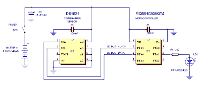
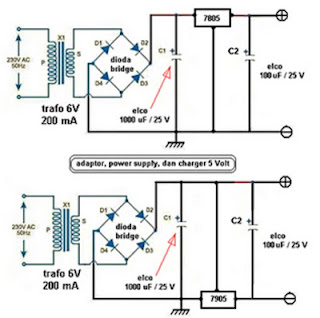
This fm synthesizer circuit is played with and optimised design for an 88-108 MHz synthesiser, programmable in 25 kHz steps. It produces about 50 mW output (and thus feeds nicely into the amplifier shown below) with no tuning required other than to set the inputs of the divide-by-N counter to the wanted frequency.
Thursday, November 20, 2014
Ultrasonic Position System
The ultrasonic position system uses ultrasonic transmitters/receivers to triangulate position of the robots used in GE423. Each of three transmitters uses a distinct frequencies: 23 kHz, 31 kHz, and 40 kHz. The 2812 DSP is used to measure signal timing and calculate position based on these values. The design of the electronics, as well as discussion of the software development is presented below.
1.0 Hardware
1.1 Ultrasonic Transmitters/Receivers
1.2 Transmit Circuit
A schematic of the transmit circuit looks like:Images of the perf-boarded transmit circuits:
Details on the components of the transmit circuit can be found in the subsection below:
1.2.1 Frequency Generation
The transmit circuit take from the Massa Website looks like:1.2.2 555 Timer Circuit
The documentation for the 555 timer can be found here. An a picture of how it is wired can beSource:http://www.williamson-labs.com/480_555.htm
Using the handy calculator for Ra, Rb, and C found here, Ra=100k ohm, Rb=200k ohm, and C=2.2 mircoF.
1.2.3 Driver Signal Circuit
The 35 Vdc supply is manufactured by Ultravolt, part number 1/4Aa24-P30. This supply is actually a 0-250 Vdc supply that uses a potentiometer to control voltage output.. The transistor used is an IRF520 n-channel MOSFET.1.3 Receive Circuit
A block diagram of the receive circuit can be seen below:And a picture of the perf-boarded receive circuit can be seen below:
Details on the components of the receive circuit can be found in the subsection below:
1.3.1 Low Signal Amp Circuit
An instrumentation amplifier made by Analog Devices was used to amplify the low signal output of the ultrasonic receivers. The actual part used was the AD620, one is recquired for each receive channel. Analog has a nice tool here, to size the gain resistor, Rg. Based on experiments, a gain value of 33 was chosen, resulting in a Rg of 1.5k ohm. The AD620 was wired as follows:1.3.2 Comparator Circuit
The analog comparitor used was part number LM339. The volatage divdier was powered using +5 Vdc to creat the digital level output signal. The output from each instrumentation amplifier was wired to the "+" terminal, and the "-" was wired to 3 volts. The 3 Vdc signal was created from the +15 Vdc supply using a voltage divider. The output of the comparitor was wired to a 5 Vdc via a 3k resistor.2.0 Software
The timing of the hardware interrupts from the 2811 is calculated, and from the times, position is calculated in the 2D plane using a combination of least squared fit and Jacobian iteration.
2.1 Matlab Triangulation Code
The first algorithm was developed using Matlab. This code can be found here. The algorithm is not stable for all input parameters, a good set of test conditions are:[x,y]=blah(.010,.012,.012)
[x,y]=blah(.009,.014,.012)
[x,y]=blah(.011,.011,.011)
Note the highly descriptive function named blah
2.2 DSP C Code
The c code for the 2812 DSP is in the attached zip file. The code works as following:- Hardware interrupt pin get triggered
- Record absolute clock time when pin transition occurs
- Go back to step 1,and once all three pins have been triggered:
- (only do this step the first time through the code) Assume robot stationary, acquire base transmit period for each frequency by averaging first 4 values, this step syncs the clocks of the transmitters to the robot
- Calculate time from transmitter to robot for each frequency
- Triangulate position of robot using least squared fit to data points
- Wait for fixed amount of time, ignore hardware interrupts during this time because of the nature of the transmit signal
- Go back to Step 1
3.0 Lessons Learned
- A resistor was needed in parallel with the tuning potentiometer to give better resolution
- A resistor was required in parallel with the US transmitter for the circuit to function because the transmitter is like a capacitor.
4.0 Acknowledgments
Various people and online resources aided in this project:- GE423 Lab Instructor: Dan Block
- GE423 TAs: Dave Johnson, Daniel Herring
- My officemate: Steve Tschopp
- Misc. Consultation: Tim Cargol
- Misc Websites:
- http://ourworld.compuserve.com/homepages/Bill_Bowden/555.htm
- http://www.williamson-labs.com/480_555.htm
- http://www.massa.com
- http://www.digikey.com (source for datasheets)
170W power amplifier LM4651 and LM4652
Power amplifier circuit requires supply voltages +22 V DC symmetrical 0-22V. Power Amplifier with IC LM4651 and LM4652 are often used in portable HiFi systems such as powered speakers, power subwoofer and car audio power Booter. D1, D2, D3 and D4 in series 170 watt power amplifier with LM4651 and LM4652 is a 22V zener diode.
Flip Flop Led Circuit
Temperature and Humidity Sensors
Here is a picture of temperature and humidity sensors SHT75:
The default measurement resolution of this sensor is 14 bits to 12 bits and temperature sensors for humidity sensors, can also use only 12 bit resolution and 8 bits.
Wednesday, November 19, 2014
Line Follower Robot Sensor Concept
Line Follower Robot Sensor Concept |
Audio Surround Decoder Circuit
Component List :
R1-2-7-8-12-13-18-19-20 : 47Kohm
R3-4-5-6-21-22-34-35 : 10Kohm
R9-10-11-14-15-16-17 : 15Kohm
R23-24-25-33-36 : 100ohm
R26-27-28-31-32 : 100Kohm
R29-30 : 5.6Kohm
C1-8 : 47uF/25V
C2-7-9-14-23 : 47nF
C3-6 : 1uF/100V
C4-5-10 : 33pF
C11-12-15 : 10uF/25V
C13 : 82nF
C16 : 18pF
C17 : 100pF mini adjustable capacitor
C18 : 2.2nF
C19 : 4.7uF/25V
C20 : 100nF
C21 : 10nF
C22 : 180pF
C24 : 150nF
RV1-RV2 : 2 X 10Kohm Log. pot.
RV3-4 : 10K Log pot.
D1 : 1N4148
IC1-6 : TL072
IC2-3 : TL074
IC4 : MN3101
IC5 : MN3004
IC Decade Counter 4017 Details
IC Decade Counter 4017 |
IC Decade Counter 4017 - CMOS 4000 series is a family of standard integrated circuits which implement a variety of logic functions using technology Complementary Metal-Oxide-Semiconductor, and is still used today. They were introduced by RCA as CD4000 COS / MOS in 1968, as a component with low power usage and a more flexible alternative to the 7400 series TTL logic chips.
While IC IC 4017 is a 16-pin CMOS decade counter CMOS 4000 series ICs. It takes input clock pulse at clock pin input and will make one of the ten pin output to "turn on / off" in sequence at each clock pulse changes.
Example of a simple circuit of ic 4017 is to create a series of "running LED" or LED running:
Example of a simple circuit of ic 4017 |
Mini and simple power amplifier
C2 = 100uF
C5 = 1uF
U1 = S1513
Skema Rangkaian Pengapian Motor CDI
A similar Schmitt trigger oscillator is used to trigger the SCR about 4 times per second. The power supply is gated off during the discharge time so that the SCR will stop conducting and return to its blocking state. The diode connected from the 3904 to pin 9 of the 74C14 causes the power supply oscillator to stop during discharge time. The circuit draws only about 200 milliamps from a 12 volt source and delivers almost twice the normal energy of a conventional ignition circuit.
High voltage from the coil is about 10KV using a 3/8 inch spark gap at normal air temperature and pressure. Spark rate can be increased to possibly 10 Hertz without losing much spark intensity, but is limited by the low frequency power transformer and duty cycle of the oscillator. For faster spark rates, a higher frequency and lower impedance supply would be required. Note that the ignition coil is not grounded and presents a shock hazard on all of its terminals. Use CAUTION when operating the circuit.
An alternate method of connecting the coil is to ground the (-) terminal and relocate the capacitor between the cathode of the rectifier diode and the positive coil terminal. The SCR is then placed between ground and the +340 volt side of the capacitor. This reduces the shock hazard and is the usual configuration in automotive applications.
Audio phase shift oscillator Circuit Diagram
Tuesday, November 18, 2014
Color Sensor with TSC230
TSC230 Color Sensor |
Pin Diagram |
Amplifier uses IC TDA7375A
Fund manager for the series 4 channel amplifier TDA7375A it can make use of the equalizer or tone controls. To manufacture ICs need to be considered cooling for IC TDA7375A because it will remove the heat.
MC3479 Stepper Motor Driver
The output can deliver up to 350 mA each of the two coils of a stepper motor 2 phases. The change of output state occurs in the low to high transition of the input clock pulse. The new output will depend on the exit of age and state of the digital inputs. The output L1 to L4 are the results of high currents, which when connected to a stepper motor a two-phase full-bridge two formations.
Resistors R1 and Rb, Zener diode D1 and IC2 MC14049UB are additional components that are used in the circuit. R1 is an uprising and resistance Rb is used to set the maximum output sink. Zener diode D1 provides back emf protection.
Triac Light Switch as a dimers
If you want a light reception sensitivity of this circuit can be arranged then the 3.3 MOhm resistor can be replaced with a variable resistor. For more details can be seen from the following series of images.
Triac Light Switch as a dimers Circuit Diagram |
DC Motor Controller Circuit with NE555
A PWM circuit primarily based on timer NE555 is that the heart of this circuit. NE555 is wired as an astable multivibrator whose duty cycle will be adjusted by varying the POT R1. The output of IC1 is coupled to the base of transistor Q1 that drives the motor according to the PWM signal available at its base. Higher the duty cycle the typical voltage across motor will be high which ends in higher motor speed and vice versa. modification of DC motor direction is attained using the DPDT switch S1 that on application simply toggles the polarity applied to the motor.
The parts of the Speaker
Parts of speaker |
Spieder or Damper
see also : Subwoofer Amplifier
Monday, November 17, 2014
What is LDR or Light Dependent Resistor
LDR or Light Dependent Resistor formed from cadium Sulfied (CDS) generated from ceramic powders.
In general, CDS also called conductive photo equipment, as long as the conductivity or resistance of CDS varies with light intensity. If the received light intensity is high then the barriers will also result in a high-voltage out also to be high and vice versa if the voltage is low. This is where the mechanism of the process of changing light into electricity occurs.
What is LDR or Light Dependent Resistor |
CDS does not have the same sensitivity at each wavelength from ultraviolet up to infrared. This is called the characteristic spectrum and the response given by the manufacturer. CDS are widely used in planning a series of alternating (AC) compared with photo transistors and photo diodes.
Know the Line Follower Robot
Sensor On Line Follower Robot
Sensors, can be analogous to the eye of a robot that serves to read the black line of the track robot. So that the robot is able to know when he will turn right, when he turned left and when he stopped. The sensor used is a light sensor mounted below the front of the robot, so as to find a bright line of a dark background or vice versa. Sensors used are usually photo reflector, R LD (Light Dependent Resistor), Photo Diodes and Photo Transistor - mounted on the front two or more under robotline follower. There also are using the camera as a sensor (or image sensor) to a higher-resolution readout line, making more accurate robot motion.Digital basic logic gates
DVD Player Circuits
FM Transmitter circuit using 2N2222
The FM transmitter circuit is using NPN transistor 2N2222. The L1 and C1 producess necessary oscillations Q1.The collector capacity C4, R3 and R4 resistor performs the function of the output mix theaudio to stereo player or i-emitter resistor R2 Pod.The provides sufficient stability for circuit.It also limits the collector current increse the battery.
Circuit Mobile Phone Battery Charger
Sunday, November 16, 2014
10 Minutes timer with 555
Preamplifier Switching Center Module
Parts
R1,R2,R3,R4____100K 1/4W Resistors
R5_____________560R 1/4W Resistor
SW1,SW2________2 poles 4 ways Rotary Switches
J1 to J6_______RCA audio input sockets
This Module can be a all-important accession to the Modular Preamplifier Control Center back added than two sources charge to be affiliated to the preamplifier chain.
Four aerial akin inputs can be alleged by agency of SW1 and baffled to the output. The achievement of this bore charge be affiliated by a acceptable cable to one of the two inputs of the Control Center module. In this way, a absolute of bristles inputs will be accessible to the user of this bore combination.
The Switching Control appearance additionally the so alleged "Double Bar", i.e. the achievability of acquisition to an alien unit, e.g. a recorder (tape or digital) an ascribe arresting altered from that reproduced at the time by the amplifier.
For example, you can accept in to a CD admitting the arresting advancing from a radio base through the Tuner is baffled to the recorder. This alternative is operated by agency of SW2.
As with the added modules of this series, anniversary cyberbanking lath can be adapted into a accepted enclosure: Hammond extruded aluminum cases are able-bodied ill-fitted to host the boards of this preamp. In particular, the cases sized 16 x 10.3 x 5.3 cm or 22 x 10.3 x 5.3 cm accept a actual acceptable attending back stacked. See beneath an archetype of the accessible adjustment of the advanced and rear panels of this module.
Notes:
- No power supply is necessary for this module
- The circuit diagram shows the Left channel only, so all the parts must be doubled except SW1 and SW2 which are double pole switches, i.e. ready for stereo.
Saturday, November 15, 2014
How to Build a Common-Emitter Proximity Detector
Proximity Detector Circuit |
Friday, November 14, 2014
MOBILE PHONE JAMMER CIRCUIT
- RF amplifier.
- Voltage controlled oscillator.
- Tuning circuit.
Circuit Diagram
Parts List
AM RECIEVER CIRCUIT
Performance will vary depending on stray capacitance in your layout, the inductor winding/core/length, etc. Changing values of some of the capacitors, or adding them, as well as a potentiometer in the feedback loop can help with the performance of the receiver. With such a small circuit that is affected so much by its construction and its environment, a lot of hand tuning and experimentation will be fun, instructive, and possibly necessary to make it work best.
Circuit Diagram
Parts List
Application
IC 74hc14 Arrow led indicator circuit with explanation
This arrow led indicator electronic project can be used in some dark places to show the directions . You can use to indicate direction just an illuminated arrow or a flashing light , but is much nicer if the light moves in the correct direction.
This arrow led indicator is based on 74HC14 circuit and some LEDs which are used to show the way .
For this arrow led indicator we need six series of three LEDs arranged in the shape of arrows and are connected to the outputs . Each time the lit arrows move over by one column so it appears that the arrows run from right to left.
If we want to change the speed of the moving light it’s need to change the value of C1 to C3 or R1 to R3 ( a lower value for this components decrease the time of moving lights) .
If we want a longer arrow we can mount in parallel with existing columns another columns .
For power supply we can use batteries or 6V regulated power supply .
Thursday, November 13, 2014
Water Sensor Circuit Diagram using IC 555
This is a simple water sensor/rain alarm circuit that makes an alarm when water/rain falls on its sensor. This circuit is based on NE555/LM555 IC and two transistors (Q1&Q2). For transistor Q1- BC547 or BC107 and for Q2- 2N825,BC548 or BC168 can be used in the circuit. This rain detector circuit can be supplied from voltage source of +9V-12V DC. The resistor 470K ohm is a POT/Variable resistor; it is used to adjust the sensitivity of water/rain sensor. Use a 8 ohm,0.5w-1W speaker to hearing better alarm. Less than 8 ohm speaker could be harmful for the IC 555.
Fig-1: Water Sensor/Rain alarm circuit diagram |
Water sensor PCB layout:
Fig-2: PCB layout of water sensor |
88 108 MHz PLL FM Synthesizer
LM317 Circuit
The LM317 is AN adjustable three terminal transformer that is capable of supply 1.2 to 37 volts with a secure 1.5A output current. The LM317 is prepackaged terribly} normal electronic transistor package that makes it very simple to mount in your circuits.
In addition to higher performance than mounted regulators, the LM317 series offers full overload protection out there solely in ICs. enclosed on the chip square measure current limit, thermal overload protection and safe space protection.
The LM317 makes AN particularly easy adjustable change regulator, a programmable output regulator, or by connecting a set electrical device between the adjustment pin and output, the LM317 may be used as a preciseness current regulator. provides with electronic conclusion may be achieved by clamping the adjustment terminal to ground that programs the output to one.2V wherever most masses draw very little current.
Specifications
- Guaranteed 1% output voltage tolerance (LM317A)
- Guaranteed max. 0.01%/V line regulation (LM317A)
- Guaranteed max. 0.3% load regulation (LM117)
- Guaranteed 1.5A output current
- Adjustable output down to 1.2V
- Current limit constant with temperature
- P + Product Enhancement tested
- 80 dB ripple rejection
- Output is short-circuit protected
60 Watt Guitar Amplifier Diagram Circuit
R2,R4_____________470R 1/4W Resistors
R3__________________2K 1/2W Trimmer Cermet
R5,R6_______________4K7 1/2W Resistors
R7________________220R 1/2W Resistor
R8__________________2K2 1/2W Resistor
R9_________________50K 1/2W Trimmer Cermet
R10________________68K 1/4W Resistor
R11,R12______________R47 4W Wirewound Resistors
C1,C2,C4,C5________47µF 63V Electrolytic Capacitors
C3________________100µF 25V Electrolytic Capacitor
C6_________________33pF 63V Ceramic Capacitor
C7_______________1000µF 50V Electrolytic Capacitor
C8_______________2200µF 63V Electrolytic Capacitor (See Notes)
D1_________________LED Any type and color
D2________Diode bridge 200V 6A
Q1,Q2____________BD139 80V 1.5A NPN Transistors
Q3_____________MJ11016 120V 30A NPN Darlington Transistor (See Notes)
Q4_____________MJ11015 120V 30A PNP Darlington Transistor (See Notes)
SW1_______________SPST Mains switch
F1__________________4A Fuse with socket
T1________________220V Primary, 48-50V Secondary 75 to 150VA Mains transformer (See Notes)
PL1_______________Male Mains plug
SPKR______________One or more speakers wired in series or in parallel Total resulting impedance: 8 or 4 Ohm Minimum power handling: 75W
Preamplifier circuit diagram:
P3_________________10K Log. Potentiometer
R1,R2______________68K 1/4W Resistors
R3________________680K 1/4W Resistor
R4________________220K 1/4W Resistor
R5_________________33K 1/4W Resistor
R6,R16______________2K2 1/4W Resistors
R7__________________5K6 1/4W Resistor
R8,R21____________330R 1/4W Resistors
R9_________________47K 1/4W Resistor
R10_______________470R 1/4W Resistor
R11_________________4K7 1/4W Resistor
R12,R20____________10K 1/4W Resistors
R13_______________100R 1/4W Resistor
R14,R15____________47R 1/4W Resistors
R17,R18,R19_______100K 1/4W Resistors
C1,C4,C5,C6________10µF 63V Electrolytic Capacitors
C2_________________47µF 63V Electrolytic Capacitor
C3_________________47pF 63V Ceramic Capacitor
C7_________________15nF 63V Polyester Capacitor
C8_________________22nF 63V Polyester Capacitor
C9________________470nF 63V Polyester Capacitor
C10,C11,C12________10µF 63V Electrolytic Capacitors
C13_______________220µF 63V Electrolytic Capacitor
D1,D2____________BAT46 100V 150mA Schottky-barrier Diodes (see Notes)
Q1,Q3____________BC546 65V 100mA NPN Transistors
Q2_______________BC556 65V 100mA PNP Transistor
J1,J2___________6.3mm. Mono Jack sockets
SW1,SW2___________SPST SwitchesSensitivity:
35mV input for 40W 8 Ohm output
42mV input for 60W 4 Ohm output
Frequency response:
50Hz to 20KHz -0.5dB; -1.5dB @ 40Hz; -3.5dB @ 30Hz
Total harmonic distortion @ 1KHz and 8 Ohm load:
Below 0.1% up to 10W; 0.2% @ 30W
Total harmonic distortion @ 10KHz and 8 Ohm load:
Below 0.15% up to 10W; 0.3% @ 30W
Total harmonic distortion @ 1KHz and 4 Ohm load:
Below 0.18% up to 10W; 0.4% @ 60W
Total harmonic distortion @ 10KHz and 4 Ohm load:
Below 0.3% up to 10W; 0.6% @ 60W
Treble control:
+9/-16dB @ 1KHz; +12/-24dB @ 10KHz
Brightness control:
+6.5dB @ 500Hz; +7dB @ 1KHz; +8.5dB @ 10KHz
Bass control:
-17.5dB @ 100Hz; -26dB @ 50Hz; -28dB @ 40HzNotes:
- The value listed for C8 is the minimum suggested value. A 3300µF capacitor or two 2200µF capacitors wired in parallel would be a better choice.
- The Darlington transistor types listed could be too oversized for such a design. You can substitute them with MJ11014 (Q3) and MJ11013 (Q4) or TIP142 (Q3) and TIP147 (Q4).
- T1 transformer can be also a 24 + 24V or 25 + 25V type (i.e. 48V or 50V center tapped). Obviously, the center-tap must be left unconnected.
- D1 and D2 can be any Schottky-barrier diode types. With these devices, the harmonic modifier operation will be hard. Using for D1 and D2 two common 1N4148 silicon diodes, the harmonic modifier operation will be softer.
- In all cases where Darlington transistors are used as the output devices it is essential that the sensing transistor (Q2) should be in as close thermal contact with the output transistors as possible. Therefore a TO126-case transistor type was chosen for easy bolting on the heatsink, very close to the output pair.
- R9 must be trimmed in order to measure about half the voltage supply across the positive lead of C7 and ground. A better setting can be done using an oscilloscope, in order to obtain a symmetrical clipping of the output wave form at maximum output power.
- To set quiescent current, remove temporarily the Fuse F1 and insert the probes of an Avo-meter in the two leads of the fuse holder.
- Set the volume control to the minimum and Trimmer R3 to its minimum resistance.
- Power-on the circuit and adjust R3 to read a current drawing of about 30 to 35mA.
- Wait about 15 minutes, watch if the current is varying and readjust if necessary.
Heat Sensor Circuit Diagram
Circuit diagram of heat sensor:
Fig-1: Schematic Circuit Diagram Of Heat/Temperature Sensor |
Thermistor, 110 Ohms:
Fig-2: 110 Ohms Thermistor |
Circuit Description:
You have seen, in this simple circuit diagram of heat sensor, a few number of components is used including a BC548 transistor, a 110 ohms thermistor etc.- BC548: BC548 is a TO-92 type NPN transistor, as its alternative you can use 2N2222, BC238, BC548, BC168, BC183 etc. they all have almost same characteristic.
- 110 Ohms Thermistor: A 110 Ohms thermistor is used to detecting heat. I have told already about it.
- Buzzer: A buzzer is used with +9V and collector of transistor. When the temperature/ heat exceeds a certain level then it make an alarm.
- 4.7V Zener diode: It is used to limit the emitter current of BC548.
- 9V Battery: A 9V battery is used as a single power source.
- R1, R2: A 3.3K 1/4w resistor is used as R1 and 100 ohms 1/4w as R2.
- Switch: Here in this circuit the switch used is a simple SPST switch. You can either use the switch or not, choice is yours. It is not mandatory.