Monday, January 26, 2015
Portable Microphone Preamplifier
This circuit is mainly intended to provide common home stereo amplifiers with a microphone input. The battery supply is a good compromise: in this manner the input circuit is free from mains low frequency hum pick-up and connection to the amplifier is more simple, due to the absence of mains cable and power supply. Using a stereo microphone the circuit must be doubled. In this case, two separate level controls are better than a dual-ganged stereo potentiometer. Low current drawing (about 2mA) ensures a long battery life.
Circuit Operation:
The circuit is based on a low noise, high gain two stage PNP and NPN transistor amplifier, using DC negative feedback through R6 to stabilize the working conditions quite precisely. Output level is attenuated by P1 but, at the same time, the stage gain is lowered due to the increased value of R5. This unusual connection of P1, helps in obtaining a high headroom input, allowing to cope with a wide range of input sources (0.2 to 200mV RMS for 1V RMS output).
Portable Microphone Preamplifier Circuit diagram:
P1 = 2.2K
R1 = 100K
R2 = 100K
R3 = 100K
R4 = 8.2K
R5 = 68R
R6 = 6.8K
R7 = 1K
R8 = 1K
R9 = 150R
C1 = 1uF-63V
C2 = 100uF-25V
C3 = 100uF-25V
C4 = 100uF-25V
C5 = 22uF-25V
Q1 = BC560
Q2 = BC550
Notes:
- Harmonic distortion is about 0.1% @ 1V RMS output (all frequencies).
- Maximum input voltage (level control cursor set at maximum) = 25mV RMS
- Maximum input voltage (level control cursor set at center position) = 200mV RMS
- Enclosing the circuit in a metal case is highly recommended.
- Simply connect the output of this device to the Aux input of your amplifier through screened cable and suitable connectors.

Multi Sound For Guitars
Electric guitars use coils (guitarists call them pickups or elements) to convert the vibrations of the strings into an electrical signal. Usually, a guitar has more than one element builtin, so that the musician can select with a switch which element or elements are used to generate the signal. Because of the differences in construction of the elements and the varying positions of where they are mounted, each element sounds different. The elements can be roughly divided into two categories. There are the so-called ‘single-coils’ and ‘humbuckers’. Single coil elements are elements that contain one core and coil for each string. Humbuckers can be regarded as two elements that are connected in series. Many humbuckers have four connections (actually two single-coils with two connections each).
Multi Sound - For Guitars Circuit diagram :

These two individual coils are usually interconnected with fixed wiring so that they are always used in series. The circuit proposed here offers the possibility of using a hum-bucker with four connections in no less than four different modes, each of which having its own sound. The only things that have to be changed on the guitar are the wiring and the addition of a four-position switch. The latter requires drilling holes in the guitar of course, but if there is a control cover plate (along the lines of a Fender Stratocaster, for example) then it makes sense to put the switch there. This avoids the need for drilling holes in the wood while keeping an (expensive) guitar reasonably unmarred. The schematic shows what the various things look like, electrically speaking, before and after the multisound modification.
Tuesday, January 6, 2015
Electronic Timer with display circuit

Using this electronic scheme can be built an electronic timer which can be set to measure a maximum of 60 hours.
The electronic timer allows the fixation of some intermediate time. On reaching this point, a buzzer will sound.
The circuit is built using ICM7217 integrated circuit, manufactured by Intersil, which contains a CMOS counter up / down, with 4 digits and display properly.
Friday, December 12, 2014
Lie detector schematic diagram

It's a simple lie detector that can be built in a few minutes, but can be incredibly useful when you want to know if someone is really telling you the truth. It is not as sophisticated as the ones the professionals use, but it works. It works by measuring skin resistance, which goes down when you lie.
Mosfet 1000W Power Inverter schematic

Stepper motor controller

Stepper Motor controller
The circuit is very simple and inexpensive. This is good thing because most commercial stepper motor controller ICs are quite expensive.
Phone calling Detector

This circuit was designed to detect when a call is incoming in a cellular phone (even when the calling tone of the device is switched-off) by means of a flashing LED.The device must be placed a few centimeters from the cellular phone, so its sensor coil L1 can detect the field emitted by the phone receiver during an incoming call.
Amplifier Timer Schematic Diagram
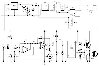
This circuit turns-off an amplifier or any other device when a low level audio signal fed to its input is absent for 15 minutes at least.Pushing P1 the device is switched-on feeding any appliance connected to SK1. Input audio signal is boosted and squared by IC2A & IC2B and monitored by LED D4.
Radio Wave Alarm

This very simple alarm circuit is sure to have the police beating a path to your door - however, it has the added advantage of alerting you to their presence even before their footsteps fall on the doormat.
Thursday, December 11, 2014
Automobile Light Fader
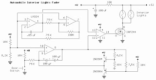
Here the circuit diagram of Interior Light Fader for Automobile.
The circuit is build using low power operational amplifier LM324 which only need around 3mA of current, so it won't bother the battery supply if left connected for extended periods.
Alarm Circuit
- A Transistor Based of Single Zone Alarm - If the building is not secure, when you switch the alarm on the buzzer will sound.
- Hijack Alarm - This circuit is designed primarily for the situation where a hijacker forces the driver from the vehicle. If a door is opened while the ignition is switched on, the circuit will trip.
- Car Alarm and Immobilizer - This circuit features exit and entry delays, an instant alarm zone, an intermittent siren output and automatic reset.
- Single Zone CMOS Alarm - This circuit has provision for normally open and normally closed switches and will accommodate the usual input devices such as Foil Tape, Pressure Mats, Magnetic Reed Contacts, Passive Infrared Detectors and Inertia (Shock) Sensors.
Thursday, November 20, 2014
Ultrasonic Position System
The ultrasonic position system uses ultrasonic transmitters/receivers to triangulate position of the robots used in GE423. Each of three transmitters uses a distinct frequencies: 23 kHz, 31 kHz, and 40 kHz. The 2812 DSP is used to measure signal timing and calculate position based on these values. The design of the electronics, as well as discussion of the software development is presented below.
The electronics were not intergrated with the 6713 DSP on the robot.
Note: To get around the issue of clock syncing, the robot will start in a known position, and calculate position for four cycles before proceeding. An alternative to this would be to add a fourth transmit frequency and use the 4th signal to sync the robot clock with the transmit clock.
1.0 Hardware
A wide variety of hardware was used for this project. The hardware was chosen based on availability and price. By no means is the solution presented "the best"or the only way to achieve the desired results, but it is a workable solution.
1.1 Ultrasonic Transmitters/Receivers
The ultrasonic sensor were purchased from Massa. The TR-89/B series where chosen because they come in 3 different frequencies, and they were stock parts. There is no pdf data sheet available on the Massa website, all information if available here. The main drawback of using Massa is there $500 minimum order, and the sensors arent cheap at about ~$30 each.
1.2 Transmit Circuit
A schematic of the transmit circuit looks like:
Images of the perf-boarded transmit circuits:

Details on the components of the transmit circuit can be found in the subsection below:
1.2.1 Frequency Generation
The transmit circuit take from the Massa Website looks like:
Source:http://www.massa.com/datasheets/graphics/tr89_data.gif
Where R1 is a 10k 10 turn precision wound potentiometer, and U1 is a CD4039B NAND Schmitt Trigger. The tuning resistor R2 and L where left out to increase the transmit power around the base frequency. The potentiometer was adjusted until the frequency was the desired base frequency. A 1k resistor was added in parallel with the potentiometer to give a higher resolution. For the 40 kHz case, a smaller capacitor was required to reach the base frequency. Make sure to tune the circuit with the ultrasonic transducers attached, because the additional impedance will change the transmit frequency. The 12 Vdc was generated by a lab supply.
The output at point TP1, is a 12V peak to peak is a square wave at the desired frequency. The point TP1 was connected to the Driver Signal Circuit presented below.
1.2.2 555 Timer Circuit
The documentation for the 555 timer can be found here. An a picture of how it is wired can be
Source:http://www.williamson-labs.com/480_555.htm
Using the handy calculator for Ra, Rb, and C found here, Ra=100k ohm, Rb=200k ohm, and C=2.2 mircoF.
1.2.3 Driver Signal Circuit
The 35 Vdc supply is manufactured by Ultravolt, part number 1/4Aa24-P30. This supply is actually a 0-250 Vdc supply that uses a potentiometer to control voltage output.. The transistor used is an IRF520 n-channel MOSFET.1.3 Receive Circuit
A block diagram of the receive circuit can be seen below:
And a picture of the perf-boarded receive circuit can be seen below:

Details on the components of the receive circuit can be found in the subsection below:
1.3.1 Low Signal Amp Circuit
An instrumentation amplifier made by Analog Devices was used to amplify the low signal output of the ultrasonic receivers. The actual part used was the AD620, one is recquired for each receive channel. Analog has a nice tool here, to size the gain resistor, Rg. Based on experiments, a gain value of 33 was chosen, resulting in a Rg of 1.5k ohm. The AD620 was wired as follows:
1.3.2 Comparator Circuit
The analog comparitor used was part number LM339. The volatage divdier was powered using +5 Vdc to creat the digital level output signal. The output from each instrumentation amplifier was wired to the "+" terminal, and the "-" was wired to 3 volts. The 3 Vdc signal was created from the +15 Vdc supply using a voltage divider. The output of the comparitor was wired to a 5 Vdc via a 3k resistor.2.0 Software
The timing of the hardware interrupts from the 2811 is calculated, and from the times, position is calculated in the 2D plane using a combination of least squared fit and Jacobian iteration.
2.1 Matlab Triangulation Code
The first algorithm was developed using Matlab. This code can be found here. The algorithm is not stable for all input parameters, a good set of test conditions are:[x,y]=blah(.010,.012,.012)
[x,y]=blah(.009,.014,.012)
[x,y]=blah(.011,.011,.011)
Note the highly descriptive function named blah
2.2 DSP C Code
The c code for the 2812 DSP is in the attached zip file. The code works as following:- Hardware interrupt pin get triggered
- Record absolute clock time when pin transition occurs
- Go back to step 1,and once all three pins have been triggered:
- (only do this step the first time through the code) Assume robot stationary, acquire base transmit period for each frequency by averaging first 4 values, this step syncs the clocks of the transmitters to the robot
- Calculate time from transmitter to robot for each frequency
- Triangulate position of robot using least squared fit to data points
- Wait for fixed amount of time, ignore hardware interrupts during this time because of the nature of the transmit signal
- Go back to Step 1
3.0 Lessons Learned
- A resistor was needed in parallel with the tuning potentiometer to give better resolution
- A resistor was required in parallel with the US transmitter for the circuit to function because the transmitter is like a capacitor.
4.0 Acknowledgments
Various people and online resources aided in this project:- GE423 Lab Instructor: Dan Block
- GE423 TAs: Dave Johnson, Daniel Herring
- My officemate: Steve Tschopp
- Misc. Consultation: Tim Cargol
- Misc Websites:
- http://ourworld.compuserve.com/homepages/Bill_Bowden/555.htm
- http://www.williamson-labs.com/480_555.htm
- http://www.massa.com
- http://www.digikey.com (source for datasheets)
170W power amplifier LM4651 and LM4652
Part of this power amplifier driver using the LM4651 IC designed specifically for the purpose of the class AB amplifier driver with short circuit protection feature, containing under voltage, thermal shutdown protection and standby functions. Section 170 Watt power amplifier using LM4651 IC with a MOSFET power amplifier is equipped with temperature sensors that will be used by IC LM4651 as controlnya thermal signal. IC IC LM4651 and LM4652 are designed specifically to each other in pairs to create a class AB power amplifier with protection features are detailed. Detailed series of 170 Watt power amplifier can be seen in thethe following figure .

Power amplifier circuit requires supply voltages +22 V DC symmetrical 0-22V. Power Amplifier with IC LM4651 and LM4652 are often used in portable HiFi systems such as powered speakers, power subwoofer and car audio power Booter. D1, D2, D3 and D4 in series 170 watt power amplifier with LM4651 and LM4652 is a 22V zener diode.
ReadMore..
Power amplifier circuit requires supply voltages +22 V DC symmetrical 0-22V. Power Amplifier with IC LM4651 and LM4652 are often used in portable HiFi systems such as powered speakers, power subwoofer and car audio power Booter. D1, D2, D3 and D4 in series 170 watt power amplifier with LM4651 and LM4652 is a 22V zener diode.
Flip Flop Led Circuit
Flip Flop LED
Flip flop circuit is a series of free runing multivibrator given the burden of LEDs on each side of the transition changes its output signal. Flip flop circuit with LEDs is quite simple, that is prepared with 2 units and 2 units of 2N3904 transistor circuit tank circuit composed by the RC circuit.
LED indicators signal a change that is placed on each side of the flip flop will be lit in turn by the fire and extinguished the same as the charge and discharge capacitor. Flip flop circuit is quite simple as shown in the picture below.

Flip Flop LED series
The working principle is the flip flop over when the series voltage source is given then the 10uF capacitor will be charged through R 470 and the LED will then be forwarded to triger the transistor base so that the transistor will turn ON and LEDs. this occurs alternately on each side, so that the LED light will illuminate in turn as well.
Temperature and Humidity Sensors
Temperature and humidity sensors used are SHT75. This sensor is a chip that can measure temperature and humidity as well. The use of these sensors with consideration of its small size and reliability. The output of this sensor has the form of digital data in the chip because it has been there for a 14bit ADC. Temperature measurement range between -40-123,8 º C and humidity between 0-100% Rh. measurement accuracy reaches ± 0.3 per increase in 25 º C for temperature and ± 1.8% RH for humidity.
Here is a picture of temperature and humidity sensors SHT75:

The default measurement resolution of this sensor is 14 bits to 12 bits and temperature sensors for humidity sensors, can also use only 12 bit resolution and 8 bits.
Here is a picture of temperature and humidity sensors SHT75:
The default measurement resolution of this sensor is 14 bits to 12 bits and temperature sensors for humidity sensors, can also use only 12 bit resolution and 8 bits.
Wednesday, November 19, 2014
Line Follower Robot Sensor Concept
Line Follower Robot Sensor Concept - Sensor line detector is used in line follower robot is usually based on the principle of light reflectionto distinguish the line with the background color. In the dark color of the light absorption is greater than that of white light reflected to the sensor becomes smaller.
Position sensor to track the trajectory and the example circuit.
| Line Follower Robot Sensor Concept |
Light used for the introduction of the line is usually visible light and infra-red. Sensors for visible light are commonly used are LDR (Light Depending Resistance), while for the infrared light is atransistor and photo diode (photodiode). Sensors placed at the bottom of the frame to hang the robot, so that its position can be located just above the track to be read.
Audio Surround Decoder Circuit
The circuit schematic drawings Surround Audio Decoder and its components and how to make it ,Audio surround decoder circuit. Surround sound quality is the process of adding the audio source by increasing the number of speakers. This is done by producing audio multitracking in a way that can be issued on a multichannel speaker.

Basically surround adopt an existing stereo system. The system uses a two-speaker stereo is right speaker and left speaker. With two speakers will be three-dimensional effect of the sound issued. With the surround, which generated three-dimensional effect was more extensive than in stereo. This is because the surround speakers that use more than two pieces. In addition to supporting the three-dimensional effects, stereo field theory is also noteworthy to organize the arrangement of sounds based on the type of sound produced.
Component List :
R1-2-7-8-12-13-18-19-20 : 47Kohm
R3-4-5-6-21-22-34-35 : 10Kohm
R9-10-11-14-15-16-17 : 15Kohm
R23-24-25-33-36 : 100ohm
R26-27-28-31-32 : 100Kohm
R29-30 : 5.6Kohm
C1-8 : 47uF/25V
C2-7-9-14-23 : 47nF
C3-6 : 1uF/100V
C4-5-10 : 33pF
C11-12-15 : 10uF/25V
C13 : 82nF
C16 : 18pF
C17 : 100pF mini adjustable capacitor
C18 : 2.2nF
C19 : 4.7uF/25V
C20 : 100nF
C21 : 10nF
C22 : 180pF
C24 : 150nF
RV1-RV2 : 2 X 10Kohm Log. pot.
RV3-4 : 10K Log pot.
D1 : 1N4148
IC1-6 : TL072
IC2-3 : TL074
IC4 : MN3101
IC5 : MN3004
Surround effects can only be listened to speakers who have more than two channels. Surround is a technique commonly used in todays films that utilize multichannel speakers. Surround allows voice can move from side to side, is a moving side to side is to move from one speaker to another speaker. To create three-dimensional sound effects you can use a series of audio surround decoder.
IC Decade Counter 4017 Details
| IC Decade Counter 4017 |
IC Decade Counter 4017 - CMOS 4000 series is a family of standard integrated circuits which implement a variety of logic functions using technology Complementary Metal-Oxide-Semiconductor, and is still used today. They were introduced by RCA as CD4000 COS / MOS in 1968, as a component with low power usage and a more flexible alternative to the 7400 series TTL logic chips.
While IC IC 4017 is a 16-pin CMOS decade counter CMOS 4000 series ICs. It takes input clock pulse at clock pin input and will make one of the ten pin output to "turn on / off" in sequence at each clock pulse changes.
Example of a simple circuit of ic 4017 is to create a series of "running LED" or LED running:
| Example of a simple circuit of ic 4017 |
Mini and simple power amplifier
What is the meaning of the picture above? The above picture is a miniature audio amplifier and very simple. Here I will give an audio amplifier schematic is very simple which only requires a few components only, can be seen under this scheme.
See from above scheme may occur to you, certainly cheap enough to make this amplifier and quite easy to make. The above simple audio amplifier circuit using an IC as the main amplifier and accompanied by other components. IC used is S1513, which requires a supply voltage ranging from 1.5 volts to 6 volts. And only 0.1 W output power with 4 ohm impedance. For a list components can be seen below.
Part list
C1 = 100nF
C2 = 100uF
C2 = 100uF
C3 = 3n3F
C4 = 1uF
C5 = 1uF
U1 = S1513
C5 = 1uF
U1 = S1513
Skema Rangkaian Pengapian Motor CDI
The CDI ignition circuit produces a spark from an ignition coil by discharging a capacitor across the primary of the coil. A 2uF capacitor is charged to about 340 volts and the discharge is controlled by an SCR.
A Schmitt trigger oscillator (74C14) and MOSFET (IRF510) are used to drive the low voltage side of a small (120/12 volt) power transformer and a voltage doubler arrangement is used on the high voltage side to increase the capacitor voltage to about 340 volts.
A similar Schmitt trigger oscillator is used to trigger the SCR about 4 times per second. The power supply is gated off during the discharge time so that the SCR will stop conducting and return to its blocking state. The diode connected from the 3904 to pin 9 of the 74C14 causes the power supply oscillator to stop during discharge time. The circuit draws only about 200 milliamps from a 12 volt source and delivers almost twice the normal energy of a conventional ignition circuit.
High voltage from the coil is about 10KV using a 3/8 inch spark gap at normal air temperature and pressure. Spark rate can be increased to possibly 10 Hertz without losing much spark intensity, but is limited by the low frequency power transformer and duty cycle of the oscillator. For faster spark rates, a higher frequency and lower impedance supply would be required. Note that the ignition coil is not grounded and presents a shock hazard on all of its terminals. Use CAUTION when operating the circuit.
An alternate method of connecting the coil is to ground the (-) terminal and relocate the capacitor between the cathode of the rectifier diode and the positive coil terminal. The SCR is then placed between ground and the +340 volt side of the capacitor. This reduces the shock hazard and is the usual configuration in automotive applications.
A similar Schmitt trigger oscillator is used to trigger the SCR about 4 times per second. The power supply is gated off during the discharge time so that the SCR will stop conducting and return to its blocking state. The diode connected from the 3904 to pin 9 of the 74C14 causes the power supply oscillator to stop during discharge time. The circuit draws only about 200 milliamps from a 12 volt source and delivers almost twice the normal energy of a conventional ignition circuit.
High voltage from the coil is about 10KV using a 3/8 inch spark gap at normal air temperature and pressure. Spark rate can be increased to possibly 10 Hertz without losing much spark intensity, but is limited by the low frequency power transformer and duty cycle of the oscillator. For faster spark rates, a higher frequency and lower impedance supply would be required. Note that the ignition coil is not grounded and presents a shock hazard on all of its terminals. Use CAUTION when operating the circuit.
An alternate method of connecting the coil is to ground the (-) terminal and relocate the capacitor between the cathode of the rectifier diode and the positive coil terminal. The SCR is then placed between ground and the +340 volt side of the capacitor. This reduces the shock hazard and is the usual configuration in automotive applications.
Subscribe to:
Posts (Atom)
